The motor plays a role in almost every part of our daily lives. They drive dishwashers and washing machines to cool the interior and are essential for modern transportation. Brushless DC (BLDC) motors have become the choice of many high-speed, high-speed systems for uniform or variable speed. With several Hall effect sensors and one controller, BLDC motors become relatively easy to control. Today, BLDC motor systems are very common, but most systems still use sensors to control the motor. To reduce the cost and reliability of BLDC systems, many designers want to remove sensors. Sensorless systems have been around for quite some time, but in the past they required expensive controllers to run the algorithms needed to remove the sensors. Digital Signal Controllers (DSCs) (such as Microchip's dsPIC33FJ15MC102, which is priced at only $1 in volume quantities) enable sensorless BLDC motor control for large-scale applications.
Sensorless BLDC control relies on the characteristics of the BLDC motor to calculate the rotor position and in this position the motor is commutated at the appropriate time. To explain how it works, let's look back at the BLDC motor itself and the basic sensor control. Fundamentally, a BLDC motor uses an excitation coil (called a stator) to create a magnetic field parallel to the coil axis on the rotor (or shaft) that causes the rotor to rotate and generate torque. In a three-phase BLDC motor, three coils (or phases) in the stator are continuously turned on and off to rotate the rotor and generate torque. In order to keep the rotor rotating, the relevant phase must be turned on and off before the rotor is rotated to the appropriate position. In order to smoothly rotate the rotor, each winding or phase constituting the motor may be composed of a plurality of sets of coils. Each phase must be turned on and off in a specific sequence to rotate the rotor. The position of the rotor determines which phase needs to be turned on or off. Therefore, understanding the rotor position is critical to the operation of the motor. In order for the BLDC motor to operate, the controller must actively turn these phases on or off. The controller must maintain the magnetic field inside the stator in front of the rotor to keep the rotor rotating. The easiest way to get the rotor position is to use Hall effect sensors that generate pulses to inform the controller of the rotor position. Once the rotor position is known, the basic BLDC controller simply looks for which of the three phases corresponds to the rotor position and switches these phases to the appropriate mode.
Relying on the operation of the sensor is very easy to implement, but removing the sensor can reduce system cost and increase reliability. To understand how the sensorless algorithm calculates the rotor position, let's take a closer look at the three phases of the BLDC motor.
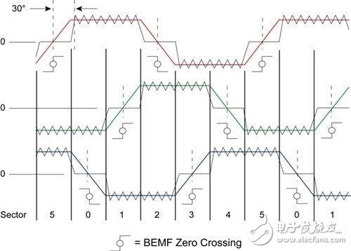
In the "ladder" control, one phase is pulled high (+VBUS) at any time, one phase is pulled low (-VBUS), and the third phase is inactive. Since the waveform of each phase is like a trapezoid (see Figure 1), the "trapezoid" control is named after it. When the rotor passes a phase, the permanent magnets on the rotor induce a current in the phase, which in turn produces a voltage called back electromotive force (EMF). The back electromotive force depends on the number of turns of each phase winding, the angular velocity of the rotor, and the strength of the rotor's permanent magnetic field. The back EMF waveform of each phase is related to the rotor position, so the back EMF can be used to determine the rotor position.

Figure 1 BLCD motor windings and trapezoidal waveforms
There are many different ways to determine rotor position using back EMF, the most common and reliable of which is zero crossing detection. When one of the back EMF signals is converted and crosses zero, the controller needs to switch the phase mode. This process is called commutation (see Figure 2). In order to keep the rotor moving forward, a phase shift must be made during the time between zero crossing and commutation, and the motor controller must calculate and compensate for this phase shift. An easy way to achieve zero crossing is to assume that a zero crossing occurs whenever the back EMF of either phase reaches VBUS/2.

Figure 2 Back EMF zero crossing
Universal Back Sticker, Back Film, TPU Back Sticker, Back Skin Sticker, PVC Back Sticker, Back Skin,Custom Phone Sticke,Custom Phone Skin,Phone Back Sticker
Shenzhen Jianjiantong Technology Co., Ltd. , https://www.tpuprotector.com