The 52xxAD family of microcontrollers integrates two programmable count array modules (PCAs) for software timers, external pulse capture, high speed output, and pulse width modulated output (PWM).
Here is mainly to introduce the PWM output function.
First, be aware of the special function registers associated with PCA/PWM applications.
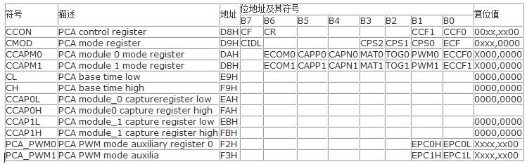
1, PCA working mode register CMOD
CIDL: Whether to stop the control bit of PCA counting in idle mode
PCA counter continues to work in idle mode when CIDL=0
PCA counter stops working in idle mode when CIDL=1
CPS2CPS1CPS0: pca counter pulse source selection control bit.
0 0 0 0, system clock SYSCLK/12
0 0 1 1, system clock SYSCLK/2
0 1 0 2, Timer 0 overflow pulse. Since Timer 0 can work in 1T mode, it can overflow when counting one clock, thus reaching the maximum frequency CPU working clock SYSCLOCK. By changing the overflow rate of Timer 0, the adjustable frequency PWM output can be realized.
0 1 1 3, external clock input to ECI/P1.2 (or P1.4) pin (maximum rate = SYSCLK/2)
1 0 0 4, system clock SYSCLK
1 0 1 5, system clock / 4, sysclk / 4
1 1 0 6, system clock / 6,
1 1 1 7, system clock / 8
2, PCA control register CCON
CF: PCA counter array overflow flag. When the PCA counter overflows, the CF is set by hardware. If the ECF bit of the CMOD register is set, the CF flag can be used to generate an interrupt. The CF bit can be set by hardware or software, but can only be cleared by software.
CR: PCA counter array run control bit, this bit is set by software to start the counter array count, cleared by software, used to turn off the PCA counter.
CCF1: pca module 1 interrupt flag. This bit is set by hardware when a match or capture occurs and must be cleared by software.
CCF0: PCA module 0 interrupt flag.
3. PCA compare/capture registers CCAPM0 and CCAPM1
ECOM0: Allows the comparator function control bit. Is 1, allowed
CAPP0: Positive capture control bit. Is 1, allowed
CAPN0: Negative capture control bit. Is 1, allowed
MAT0: Match control bit.
When 1, the match of the PCA count value with the module's compare/capture register value sets the interrupt flag bit CCF0 of the CCON register.
TOG0: Flip control bit. When tog0 = 1, it works in PCA high-speed output mode, and the matching of the value of the PCA counter with the value of the module's compare/capture register will cause the CEX0 pin to flip. (CCP0/PCA0/PWM0/P1.3)
PWM0: Pulse adjustment mode
When PWM0=1, the CEX0 pin is allowed to be used as the pulse width adjustment output (CCP0/PCA0/PWM0/P1.3)
ECCF0: CCF0 interrupt can be interrupted. The compare/capture flag CCF0 of the enable register CCON is used to generate an interrupt.
4, PCA 16-bit register - low 8-bit CL and high 8-bit CH
Used to save the load value of the PCA.
5, PCA capture / compare registers - CCAPnL (lower byte) and CCAPnH (high byte)
When the PCA modules are used for capture or comparison, they are used to hold the 16-bit capture count values ​​for each module; when the PCA module is used in PWM mode, they are used to control the duty cycle of the output. Where n=0, 1, respectively correspond to module 0 and module 1. The reset values ​​are all 00H, and the corresponding addresses are:
CCAP0_EAH CCAP0H_FAH:
CCAP1_EBHCCAP1H_FAH;
The working mode setting table of the PCA module is as follows:
ECOMn CAPPn CAPNn MATn TOGn PWMn ECCFn module function
0 0 0 0 0 0 0 no such operation
1 0 0 0 0 1 0 8-bit PWM, no interrupt
1 1 0 0 0 1 1 8-bit PWM output, interrupted by low to high
1 0 1 0 0 1 1 8-bit PWM output, interrupted by high to low
1 1 1 0 0 1 1 8-bit PWM output, can be interrupted from low to high or high to low
X 1 0 0 0 0 x 16-bit capture mode, triggered by the rising edge of CCPn/PCAn
X 0 1 0 0 0 x 16-bit capture mode, triggered by the falling edge of CCPn/PCAn
X 1 1 0 0 0 x 16-bit capture mode, triggered by a CCPn/PCAn transition
1 0 0 1 0 0 x 16-bit software timer
1 0 0 1 1 0 x 16-bit high speed output
6, PCA 16-bit counter - low 8-bit CL and high 8-bit CH
Used to save the load value of the PCA.
7, PCA capture / compare register CCAPnL (lower byte) and CCAPnH (high byte)
When the PCA module is used for capture or comparison, they are used to hold the 16-bit capture count value for each module; when the PCA module is used in PWM mode, they are used to control the duty cycle of the output. Where n=0, 1 corresponds to module 0 and module 1. The reset values ​​are all 00H. Their corresponding addresses are:
CCAP0L_EAH CCAP0H_FAH: Capture/Compare Register for Block 0
CCAP1L_EBH CCAP1H_FBH: Capture/compare register for module 1.
Pulse width adjustment mode
Plus width modulaTIon is a technique for controlling waveform duty cycle, period, and phase waveforms. It is widely used in three-phase motor drive, D/A conversion, etc.
The PCC module of the STC12C5201AD series can be programmed to operate in 8-bit PWM mode.
Since all modules share the only PCA timers, all of their output frequencies are the same. The output duty cycle of each module is independently varied and is related to the capture registers EPCnL, CCAPnL used. When the value of the register CL is less than EPCnL, CCAPnL, the output is low; when the value of the register CL is greater than or equal to the value of EPCnL, CCAPnL, the output is high. When the value of CL changes from FF to 00 overflow, the contents of EPCnH, CCAPnH are loaded into EPCnL, CCAPnL, thus implementing the interference-free update PWM. To use PWM mode, the PWMn and ECOMn bits of the CCAPMn register of the module must be set.
Since the PWM is 8-bit, the frequency of the PWM = PCA clock input source frequency / 256
The PCA clock input source can be selected from the following: SYSCLK SYSCLY/2SYSCLK/4SYSCLK/6 SYSCLK/8SYSCLK/12 Timer 0 overflow, ECI/P3.4 input.
If you want to achieve adjustable frequency PWM output, you can choose the overflow rate of timer 0 or the input of ECI pin as the clock input source of PCA/PWM.
When EPCnL=0 and CCAPnL-00H, the PWM fixed output is high.
When EPCnL=1 and CCAPnL=FFH, the PWM fixed output is low.
When an I/O port is used as a PWM, the status of the port is changed.
State of the PWM port before the state of the PWM output port
Weak pull-up / quasi-bidirectional strong push-pull output / strong pull-up output, to add output current limiting resistor 1K-10K
Strong push-pull output / strong pull-up output strong push-pull output / strong pull-up output, to add output current limiting resistor 1K-10K
Only input / high resistance PWM is invalid
Open drain open drain
Below is a C language example in the STC manual.
#include
#include "intrins.h"
#define FOSC 12000000L
Typedef unsigned int WORD;
Typedef unsigned char BYTE;
Sfr CCON=0xd8;//PCA control register
Sbit CCF0=CCON^0;//PCA module_0 interrupt flag
Sbit CCF1=CCON^1;//pca module_1 interrupt flag
Sbit CR=CCON^6;//pca TIme run control bit
Sbit CF=CCON^7;//PCA TImer overflow flag
Sfr CMOD=0xd9;//pca mode register
Sfr CL=0xe9;//PCA base TIme low
Sfr CH=0xf9;//PCA base time high
Sfr CCAPM0=0XDA;//PCA module_0 mode register
Sfr CCAP0L=0XEA;//PCA module_0 capture register low
Sfr CCAP0H=0XFA;//PCA module_0 capture register high
Sfr CCAPM1=0XDB;//PCA module_1 mode register
Sfr CCAP1L=0xeb;//PCA module_1 capture register low
Sfr CCAP1H=0XFB, //PCA module_1 capture register high
Sfr PCAPWM0=0XF2;
Sfr PCAPWM1=0XF3;
Void main()
{
CCON=0;//initial PCA control register
//PCA timer stop running
//clear CF flag
//clear all module interrupt flag
CL=0;//reset PCA base timer
CH=0;
CMOD=0X02;//set PCA time clock source as fosc/2
//disable PCA timer overflow interrupt
CCAP0H=CCAP0L=0X80;//PWM0 port output 50% duty cycle sequare wave
CCAPM0=0X42;//PCA module_0 work in 8_bit PWM mode
// and no PCA interrupt
CCAP1H=CCAP1L=0XFF;//pwm1 port output 0% duty cycle square wave
PCAPWM1=0X03;//
CCAPM1=0X42;//PCA module_1 work in 8_bit PWM mode and no PCA interrupt
CR=1;//PCA timer start run
While(1);
}
Water Cooler Condenser
1.there are many models
1.wire tube condenser,bundy tube refrigerator condenser,Freezer Condenser,refrigerator condensor,deep freezer condener,Wire On Tube Condenser,refrigerator wire on tube condenser,bundy tube refrigeration condenser,domestic refrigerator condenser
Structure:
A.Flat type of wire on tube condenser used at the back
B.Bended or spiral type of wire on tube condenser used at the bottom
C.Wrapped type of tube condenser embed on plate
Main Production Process:Tube Bending,Welding,Fix the Bracket,Weld the suction tube,Leakage Test,Coating,Folding or bending shaping,Inspection,Package
Technical Ability:Wire Pitch≥5mm
We can produce according to the drawing or sample supplied by clients,also can help the clents design and produce different condensers
Water Cooler Condenser,Freezer Condenser Coils,Water Cooled Condensing Unit,Refrigerator Compressor Condenser
FOSHAN SHUNDE JUNSHENG ELECTRICAL APPLIANCES CO.,LTD. , https://www.junshengcondenser.com