Introduction
There are two main types of PWM control: voltage-mode and current-mode. In voltage-mode PWM, the controller adjusts the pulse width based on the feedback voltage. In current-mode PWM, it uses the feedback current to adjust the output pulse width. This method is especially useful in power supplies where precise control of both voltage and current is required.
1. How a Dual-loop Current-mode PWM Controller Works
The dual-loop 24V power supply current-mode PWM controller adds an additional layer of control by monitoring the inductor current. It combines the functions of a traditional voltage-mode controller with a current feedback loop, allowing for more accurate and stable regulation. The circuit design is shown in Figure 1, which illustrates how the system operates using both voltage and current feedback signals.
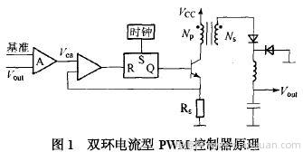
As seen in Figure 1, the 24V current-mode controller has two closed loops: one for voltage feedback and another for current sensing. The error amplifier compares the output voltage with a reference voltage, generating an error signal. This signal is then compared with the sensed inductor current to adjust the duty cycle, ensuring that the peak inductor current follows the error voltage. This dual-loop system improves the overall performance of the power supply in terms of voltage regulation, load response, and stability.
2. Key Features of Dual-loop Current-mode PWM Controllers
a) The input voltage change is immediately reflected in the inductor current, allowing for fast adjustment of the pulse width without relying on the error amplifier. This leads to excellent line regulation, often reaching 0.01%/V or better.
b) The high gain of the feedback loop ensures stable operation without compromising performance, resulting in precise output voltage control.
c) A current-limiting feature is built-in by detecting the voltage across a resistor (Rs). When this voltage reaches 1V, the PWM controller turns off instantly, protecting the switch from overcurrent conditions during overload or short circuits.
d) The error amplifier helps regulate the output voltage when the load changes, reducing voltage overshoot and improving load regulation significantly.
e) The current loop allows for easy implementation of parallel current sharing by comparing the current-sampling signal with the error amplifier output, enabling multiple power modules to work together efficiently.
3. Power Factor Correction Using Dual-loop Current-mode PWM
Thanks to its advanced features, current-mode PWM controllers are widely used in modern power supplies. They support power factor correction (PFC), which reduces harmonic distortion and improves energy efficiency. This makes them ideal for applications requiring clean and efficient power delivery.
3.1 Power Factor Correction Methods
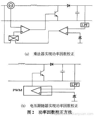
There are two main approaches to PFC: one involves adding a converter on the grid side to compensate for reactive power, while the other modifies the rectifier circuit to shape the input current into a sine wave that matches the grid voltage. These methods can be implemented in continuous conduction mode (CCM) or discontinuous conduction mode (DCM) using multipliers and voltage followers, as shown in Figure 2.
3.2 Power Factor Correction with Current-mode PWM
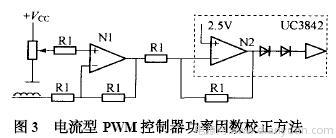
Instead of using expensive multipliers, an adder circuit is often used to replicate their function. To ensure the inductor current waveform is sinusoidal, the input to the current sense comparator must be a sine wave. The basic circuit is illustrated in Figure 3.
Dustproof Laser Level,High Precise Laser Level,Laser Spirit Level,Construction Level Laser
Guangdong Tumtec Communication Technology Co., Ltd , https://www.gdtumtec.com