Introduction
PWM (Pulse Width Modulation) is a widely used technique in power electronics to control the amount of power delivered to a load. There are two main types: voltage-mode PWM and current-mode PWM. In voltage-mode PWM, the controller adjusts the pulse width based on the feedback voltage, while in current-mode PWM, it uses the feedback current to adjust the output. This method provides better stability and faster response, making it ideal for high-performance power supplies.
1. How a Dual-loop Current-mode PWM Controller Works
The dual-loop 24V power supply current-mode PWM controller integrates both voltage and current feedback within a single control loop. It not only performs the functions of a traditional voltage-mode controller but also monitors the inductor or switching current. This allows for double-loop control, enhancing system performance. The circuit principle is illustrated in Figure 1.
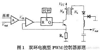
As shown in Figure 1, the 24V current-mode controller has two closed loops: one is the output voltage feedback error amplifier that compares with a reference voltage to generate an error signal; the other is the current feedback from the primary side of the transformer or inductor. This current is compared with the error voltage to modulate the pulse width, ensuring that the peak inductor current follows the error voltage.
The system operates as follows: If the input voltage drops, the rectified DC voltage decreases, leading to a drop in the output voltage due to inductance delay. The error amplifier detects this delay, causing the Vea (error voltage) to rise, which then adjusts the duty cycle to maintain a stable output. As the input voltage decreases, the peak inductor current also drops, reducing the di/dt slope. This causes the ramp voltage to reach Vea later, increasing the PWM duty cycle and stabilizing the output. This dual control mechanism ensures excellent performance in real-world applications.
2. Characteristics of a Dual-loop Current-mode PWM Controller
a) Since changes in the input voltage Vi are immediately reflected in the inductor current, the output pulse width can be adjusted without relying on the error amplifier, resulting in a very good voltage regulation rate of up to 0.01%/V, which is much better than linear regulators.
b) Due to the fast response and high stability of the dual-loop system, the feedback loop gain can be high without compromising stability, leading to precise output voltage control.
c) The peak inductor current is sensed through Rs. When the voltage across Rs reaches 1V, the PWM controller turns off immediately, creating a pulse-by-pulse current limit. This protects the main switch during overload or short-circuit conditions by keeping the peak current within a safe range.
d) The error amplifier helps regulate the output voltage when the load changes, significantly reducing the voltage overshoot when the load decreases, thereby improving the load regulation rate.
e) The inner current loop acts as a well-controlled current amplifier, allowing for parallel current sharing by comparing the current sampling signal with the output of the voltage error amplifier, enabling efficient multi-channel power distribution.
3. Power Factor Correction with Dual-loop Current-mode PWM Controllers
Thanks to these advantages, current-mode PWM controllers are increasingly used in practical applications. They incorporate power factor correction (PFC) technology, which reduces harmonic distortion and improves energy efficiency. This makes them highly valuable in modern power systems.
3.1 Power Factor Correction Methods
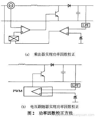
There are two main approaches to PFC: one involves using a common power converter on the grid side to compensate for reactive power and harmonics; the other adds a power conversion circuit between the rectifier and filter capacitor to shape the input current into a sine wave that matches the grid voltage. PFC can be implemented in both Continuous Conduction Mode (CCM) and Discontinuous Conduction Mode (DCM) using multipliers and voltage followers, as shown in Figure 2.
3.2 Power Factor Correction Using Current-mode PWM
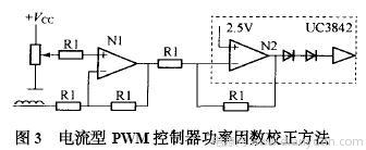
Since multipliers are expensive, an addition circuit is often used instead to simulate their function. To make the inductor current waveform sinusoidal, the inverting input of the current sense comparator must receive a sinusoidal signal. The basic circuit is shown in Figure 3.
Laser Level Tripod,Laser-protected Glasses,Mechanical Fiber Splice,Fiber Optic Mechanical Splice
Guangdong Tumtec Communication Technology Co., Ltd , https://www.gdtumtec.com