Introduction LabView has been widely used as a graphical interface development platform for embedded applications. The DS3900 serial communication module is a universal interface board. With the help of this interface board, users can use the PC serial port to communicate with devices with I²C interfaces. The DS3900 instruction set allows application software to communicate directly with I²C devices.
This application note is a user guide for the LabView interface of DS3900. First, users need to install LabView. Standard VIs are provided for users to load and run programs. You can download the LabView code (ZIP, 321K) associated with this application note.
After loading the VI using LabView software, the user must run the program and follow the steps below. (see picture 1)
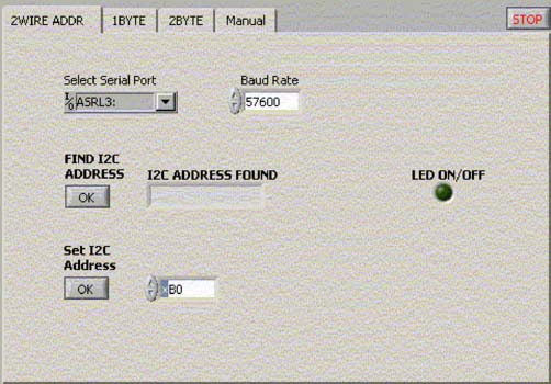
Figure 1. LabView interface through which the user configures the system to prepare for work
The user must first select the serial port to which the DS3900 is connected. LabView automatically searches all available serial port resources and displays these serial ports in the drop-down list. Select the serial port to which the DS3900 is connected.
Note: The default baud rate for communication with the DS3900 is 57600. This application has been tested at this baud rate and works properly. Users are advised not to change this baud rate when using this application. After setting the serial port correctly, you can use the LED on / off function normally. If the terminal application connects the LED to the pulse output port (P3 pin) of the DS3900, the LED flashes when the LED on / off button is pressed. Next, by clicking the FIND I2C ADDRESS button, find all device addresses connected to the I²C bus. Type the address of the slave device that will communicate with the VI in the Set I2C Address input box. Use the tab at the top of the window to select the function you want to use. Provide multiple functional options: 1BYTE: read or write a register, 1 byte at a time. 2BYTE: Read or write two consecutive memory addresses. We assume the following situation: After each read or write operation is completed, the device's internal address counter automatically increments. Manual: It allows users to control how the I²C bus operates. Some examples are given in the manual control section below. Single byte read / write operation
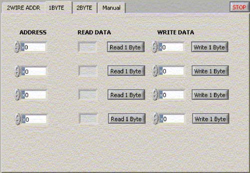
Figure 2. When performing single-byte read / write operations, the user can select four addresses to communicate with the I²C device.
The user can select four different addresses for communication (Figure 2). Any READ DATA results will be copied to the corresponding WRITE DATA input box, in order to facilitate the processing of each data bit.
Double byte read / write operation
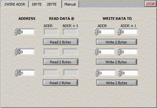
Figure 3. The 2BYTE tag allows users to read data from two registers.
For some specific devices, a register may include two consecutive bytes in memory. If the device's memory address pointer can be automatically incremented to point to the next register, the 2BYTE tag (Figure 3) allows the user to read two consecutive registers. The read data will be automatically copied into the WRITE DATA TO input box.
Manual control
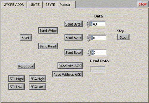
Figure 4. The MANUAL control tag allows the user to define the number of bytes of operation and the desired read or write operation.
The user uses the MANUAL control option (Figure 4) to determine the number of bytes and required operations. Examples of standard single-byte write operations and double-byte read operations are given below.
Single byte write operation
| START | SEND WRITE (DEVICE ADDRESS FOR WRITE) | SEND BYTE (MEMORY ADDRESS) | SEND BYTE (DATA TO BE WRITTEN) | STOP |
Double-byte read operation
| START | SEND WRITE (DEVICE ADDRESS FOR WRITE) | SEND BYTE (MEMORY ADDRESS) | SEND START (REPEATED START) | SEND READ (DEVICE ADDRESS FOR READ) | READ WITH ACK (READ 1ST BYTE) | READ WITH NACK (READ 2ND BYTE) | STOP |
Important note: When reading data, the last byte read should use "Read with NACK". This allows users to read as many bytes as needed. "Read with NACK" is required to tell the device not to send any more data.
The user can reset the I²C bus. This function is very useful if the user does not know how to operate during the manually controlled communication process and the bus is in an unknown state. The SCL and SDA High / Low buttons allow the user to force these pins to the desired state.
Summary This application note, combined with the LabView VI provided, explains the great role LabView plays when communicating with the DS3900. Once these basic concepts are understood, users can modify VIs or copy specific modules to meet specific application requirements.
APPLICATIONS
DELIGHT lighting pole is ideal for pedestrian, street, highway and other general lighting applications. 2m-4m for garden, parks, pedestrian streets. 5m-12m for roads, highway.12m-30m for plazas, airport, seaport, squares
MATERIAL
Q235, Hot-dip galvanized steel, galvanized plating on both of side of pole. Zinc plating 120-130 micron average. Steel anchor bolt with bolts & screws. Hand pole,
SHAPE
Tapered, Square, Octagonal, Hexagonal, Conical, Round
DEMENSION
Top diameter & bottom diameter, thickness customized, while we will provide proposal according to application condition
FINISH
Finishes include hot dip galvanized or painted. Please consult factory for special finishing color and fixture matching options
Street Light Pole,Light Pole,Street Pole,Yard Light Pole
Delight Eco Energy Supplies Co., Ltd. , https://www.cndelight.com