Design and application of TPMS system integrating CAN and LIN communication functions
introduction
This article introduces the design method of TPMS software and hardware in detail through the design and application of TPMS on a foreign vehicle model. In this scheme, the design of CAN and LIN bus is integrated, which meets the vehicle wiring requirements of TPMS in actual application, and is integrated with the vehicle bus, which truly realizes the systemization and intelligence of TPMS.
Project requirement analysis and TPMS system plan design
The design of TPMS is a system engineering. In addition to the design of the product itself, more attention needs to be paid to its application environment-the car itself, from the aspects of TPMS installation, wiring, function, performance, communication, interference, etc., to clarify the TPMS design Requirements, determine its technical solutions.
TPMS technical needs analysis
According to the specific environment of the vehicle, the special technical requirements of TPMS are analyzed as follows:
a) Radio frequency signal transmission is a key technology in the TPMS system. When the transmission signal in the tire is to be transmitted to the receiving system in the car, first of all, the tire must cause signal attenuation. Secondly, the metal shell of the vehicle itself is equivalent to a shielding box, which will cause the TPMS signal to be very unstable. Especially for the high-end models targeted in this project, vehicles have a greater impact on RF signals.
b) The tire pressure sensing module in the tire is the core content of the TPMS design. Due to the harsh application environment in the tire, its design faces many difficulties.
c) In the design of this project, the original car has the communication function of 1Mbps high-speed CAN, so TPMS must be integrated with the CAN bus of the whole car to realize the informationization and intelligent control of the system.
TPMS application design
The TPMS system includes: four tire pressure sensing modules, an ECU main control module, two radio frequency digital antenna modules, and CAN / LIN communication wires. The information processing and transmission process is shown in Figure 1.
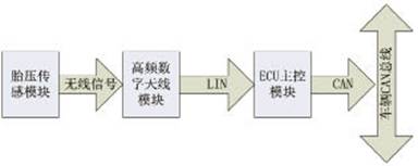
Figure 1 TPMS signal processing flow
Transmitter module design based on NPX1 sensor chip
Hardware circuit design of sensor module
NPX is an integrated chip of high-precision sensor and low-power single-chip microcomputer. It is a special chip used in TPMS. It has obvious advantages such as perfect function, reliable performance and flexible application. Mainly realize the process of tire pressure / temperature measurement, signal amplification, A / D conversion, data calculation and calibration, digital signal encoding output, etc.
T5754 is a high-gain output RF chip. ASK / FSK modulated signals can be realized through different peripheral circuit designs. The external crystal oscillator Y1 provides the reference frequency for the chip. After 32 times of different frequencies, different frequencies can achieve 315MHz or 434MHz RF signals.
Figure 2 is a schematic diagram of the tire pressure sensing module. The software sets P14 as the data stream output port. The high and low levels of the data stream continuously switch the collector transistor Q1 on and off, and the load capacitance C7 of the crystal Y1 is reached || The capacitance value of C8 changes, thereby affecting the resonant frequency of the crystal oscillator and realizing the modulation function of FSK. In addition, C1, L1, and R1 in the circuit are connected in parallel to form a low-frequency interface, which is dedicated to receiving 125kHz low-frequency signals, which can realize the active wake-up of the tire pressure sensor for function detection or two-way communication.
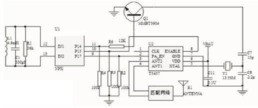
Figure 2 Schematic diagram of the sensor module
Sensor module firmware programming
The firmware programming of the sensor module is mainly designed around power saving and reliability. For the special application of TPMS, NXP has interrupt functions such as ITOV, LTOV, LF WUP, etc., so that the entire transmitting module can be in a dormant state most of the time, and only in a short working state when an interrupt occurs.
Figure 3 is a flowchart of the firmware program. ITOV is a 4s timed interruption of the main line workflow. When the vehicle is running, the tire pressure and temperature data can be sampled at 4s intervals, and according to the system judgment, wireless transmission of tire pressure and temperature information can be realized; LTOV is a 200µs timed interruption. When ITOV and LTOV work together to open and close the low-frequency window, the low-frequency window of 200µs can be opened every 4s, waiting for the low-frequency signal to wake up, which can greatly reduce the power consumption of the entire sensor module; WUP is the low-frequency signal to wake up Interruption, when the external device sends a 125kHz low-frequency signal, the sensor module will be woken up, receive low-frequency data, and send a radio frequency signal according to the low-frequency command to realize the detection of the sensor module by the external device. In addition, this low-frequency function is also used in the two-way communication of TPMS, which can realize the active inquiry of the sensor module by the TPMS receiving module.
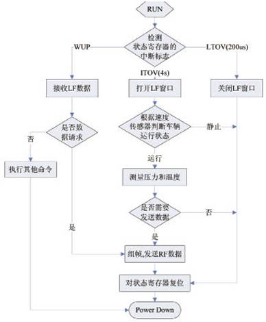
Figure 3 Program flow of the sensor module
Design of TPMS receiving system integrating CAN and LIN
This TPMS receiving system has strong system expansibility. Especially for the design of radio frequency digital antennas, the designers must make a reliable evaluation of the radio transmission environment of the specific vehicle to determine the number of radio frequency digital antenna nodes on the LIN bus. In addition, according to the system design requirements, four low-frequency wake-up modules are extended on the LIN bus. As shown in Figure 4, the blue parts are the extended modules on the LIN bus, which are installed near the tires respectively, and sent by the ECU main control module to the four low-frequency wake-up modules. The low-frequency wake-up module sends a low-frequency signal to activate the pressure sensing module in the tire to realize the two-way communication of TPMS, so that the ECU main control module can actively and real-time query the tire information.
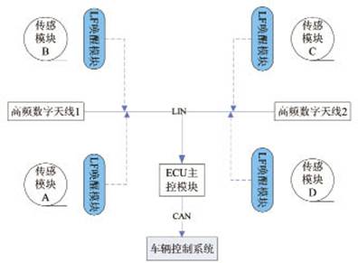
Figure 4 LIN bus expansion diagram
In the design of this project, TPMS is designed as a one-way transmission system according to customer needs and system radio environment, and two radio frequency digital antennas are installed at the front and back of the chassis.
ECU main control module hardware circuit design
Figure 5 shows the principle design diagram of the ECU main control module. MC9S08DZ16 is a high-performance 8-bit single-chip microcomputer launched by Freescale. It uses HCS08 core, the maximum operating frequency can reach 40MHz, and has rich equipment resources such as CAN and LIN.
TJA1050 is a high-speed CAN transceiver with a data transfer rate of up to 1Mbps; TJA1020 is a LIN transceiver with a rate of up to 20kbps. Both of these chips are bus driver chips launched by Philips and have strong EMC performance and transmission stability.
In this module design, the circuit design of high-speed CAN is a key step, which is directly related to the compatibility and reliability of the communication between TPMS and vehicle system. The design points are summarized as follows:
a) PCB design: In the application of high-speed CAN, the wiring of CAN components is crucial in PCB design. On the one hand, it is necessary to ensure that the transmission line of high-speed CAN is as short as possible, the wiring is compact, and the distributed capacitance is small, to reduce the loop area , To enhance anti-interference performance; on the other hand, to ensure the smoothness of high-speed signals, to avoid routing bends and crosses, it is easy to cause signal crosstalk and instability. Practice has proved that a PCB with reasonable wiring not only has stable signals but also has a long transmission distance.
b) Load matching: In CAN network design, node and bus load matching are very important indicators, especially for high-speed CAN design should pay more attention. As a node of CAN network in automobile system, TPMS load design must fully consider the design requirements of system bus.
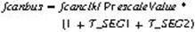
c) Transmission rate configuration: Each bit in CAN signal transmission is composed of three parts, namely SYNC_SEG, T_SEG1, T_SEG2, we must take into account the transmission rate, sampling points and other system requirements for reasonable register configuration of the CAN controller.
In this system, as shown in Fig. 5, select the external crystal oscillator Y1 to provide the CAN controller with a clock signal of fcanclk = 8MHz, and configure SYNC_SEG = 1, T_SEG1 = 4, T_SEG2 = 3 through the register, and the bus prescaler Prescale Value = "1" .
CAN bus rate
Sampling point
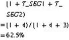
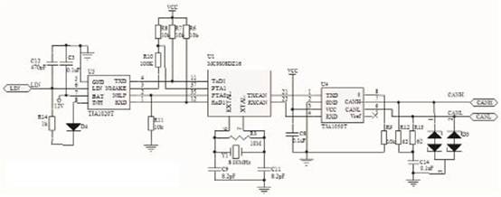
Figure 5 Schematic diagram of ECU main control module
d) CAN bus simulation and testing: After the CAN bus software and hardware design is completed, basic function, performance simulation and testing are necessary processes. In this project, the Kvaser CAN bus diagnostic tool is used for simulation testing, which can simulate the information exchange between the tested node and other CAN nodes on the network and track the data transmission on the CAN bus in real time. In addition, the diagnostic tool can be used to randomly send interference data streams to the CAN bus to test the reliability of data on the CAN bus.
Figure 6 shows the data simulation test of the CAN tool. The data frames 0x343, 0x344, 0x345 marked by the red line are the tire information and TPMS system status information sent by the ECU main control module of the TPMS to the vehicle system; the data frame 0x1A0 marked by the blue line is the speed information sent by the simulated vehicle system to the TPMS; other The data frame is an interference data frame sent randomly by the emulator on the bus.
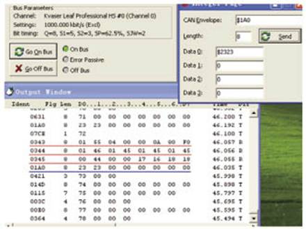
Figure 6 CAN bus simulation test chart
Hardware circuit design of radio frequency digital antenna
The principle of the radio frequency digital antenna is shown in Figure 7, which is mainly composed of a radio frequency receiving chip, a single chip microcomputer, and a LIN transceiver chip. MC33594 is a high-sensitivity OOK / FSK receiver chip with automatic gain control. It is mainly responsible for the reception and demodulation of radio frequency signals, and transmits data to the MC9S08SG8 microcontroller through the SPI interface in an interrupted manner. The microcontroller processes the data to form LIN Data packets. When a host requests data on the LIN bus, the LIN data packet will be sent to the LIN bus through the TJA1020.
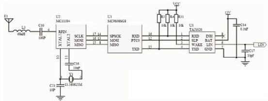
Figure 7 RF digital antenna schematic
The message frame of the LIN bus is composed of the message header and the response field. The waveform analysis diagram is shown in Figure 8. The packet header is sent by the host and includes a synchronization interval field, a synchronization field and an identifier field, where the identifier field is the event command sent by the host to the slave. After receiving the command, the slave sends or receives 8 bytes of data and checksum according to the protocol, which constitutes the response field. In this way, one-by-one access and information transfer from the master to each slave are completed.
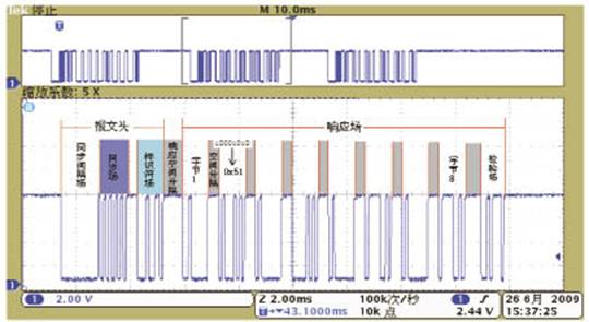
Figure 8 LIN data waveform analysis diagram
LIN bus is a network structure of single master and multiple slaves. In the LIN bus design of this system, it mainly realizes the configuration of the two radio frequency digital antennas (slave) of the ECU main control module (master) and the reading of tire data. Figure 9 shows the triggering work diagram of the information event on the LIN bus.
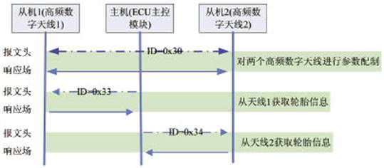
Figure 9 LIN bus event trigger diagram
The firmware program design of TPMS receiving system
Figures 10 and 11 are flowcharts of the firmware program of the RF digital antenna and the ECU main control module, respectively. The radio frequency digital antenna mainly receives the radio frequency data in the SPI interrupt mode, and sends the LIN data frame in the LIN request interrupt mode. The ECU main control module works in a timed query mode: actively sends CAN data frames every 1s; actively queries the data of the RF digital antenna every 2s; and actively detects the internal faults of the TPMS system every 30s. In addition, the ECU main control module can receive the data on the CAN bus in an interrupted manner to realize the registration of the TPMS transmitter module ID, parameter setting, and vehicle information sharing.
Shanghai Baolong Automobile Technology Co., Ltd. Han Wenbin Han Yunxiao Gaofeng
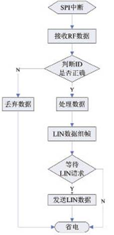
Figure 10 RF digital antenna flow chart
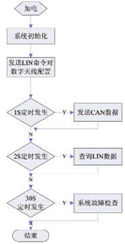
Figure 11 RF digital antenna flow chart
Design verification
The TPMS design is an automotive safety system with very high reliability requirements. A strict and scientific reliability verification plan must be formulated from the perspective of failure analysis, including laboratory tests and on-site durability sports car tests. As shown in Figure 12, when the TPMS is installed on a foreign car for a durable sports car, a CAN analyzer is used to continuously collect and track CAN data. Four different color curves represent the air pressure of each tire in the vehicle during operation Changes, as can be seen from the figure, TPMS system can monitor tire pressure very accurately and reliably.
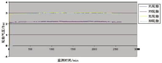
Figure 12 TRMS system sports car test data tracking diagram
Conclusion
Guided by customer needs, this article describes a reliable TPMS technical solution, and introduces the design ideas and steps of TPMS in detail from typical application processes such as system analysis, program construction, module design, system debugging, and project verification. Although the system has a complex layout and many modules, it completely solves the problem of severe failure of TPMS wireless signal instability. According to the specific requirements of the vehicle environment, the system can be effectively reduced or expanded to meet the flexible design of different vehicle models. However, the design of TPMS is a complicated process after all. Especially in the application of different automotive environments, it still faces many problems, and further research is needed to make TPMS more reliable and intelligent for automotive safety.
Drum type Rice Cooker
Features
This type rice cooker is famous with drum type appearance, which is easy operation and easy clean.
There are two type of inner pot , one type called white pot which is without non-stick but cheaper price .another one called non-stick pot is polished with emery, Also there are two type non-stick with different price ,it`s depending on different demands to use.
And the inner pot cannot be burned on the stove, which will make the pot transfigured and bad contact with the heating plate. While cooking , the heating plate or the fuse is most likely to be burned for the bad contact of the inner pot and the heating plate, Besides, make sure to dry the pot before putting into the outer shell of the rice cooker ,or else the drops of water flowing on the heating plate, will make the heating plate rusted.
Applications
Many peoples are used drum type rice cooker for congee and soup, some of peoples are prefer to use this type rice cooker for steaming.
Drum Rice Cooker,Drum Shape Rice Cooker,Electric Drum Rice Cooker,Multifunctional Drum Rice Cooker
Guangzhou Taipeng Electrical Appliances Technology CO., LTD. , https://www.kettles.pl