TV signal spectrum characteristics
The TV system completes the decomposition and synthesis of the image through line and field scanning. Although the image content is random, the TV signal still has the quasi-periodic characteristics of line, field or frame. Through spectrum analysis of the still image TV signal, it can be seen that it is composed of the fundamental wave of the horizontal frequency and the field frequency and their respective harmonics, and its energy is symmetrically distributed on both sides of each harmonic of the horizontal frequency at the interval of the frame frequency . For the television signal of the moving image, the frequency spectrum distribution is a continuous comb-like spectrum centered on the horizontal frequency and each harmonic, as shown in Figure 07-03-3.
Fig. 07-03-3 Frequency spectrum of active image TV signal
For an actual television signal, the higher the harmonic order, the greater the attenuation relative to the fundamental amplitude. In the entire frequency band of the television signal, the area without energy is much larger than the area with energy. According to this property, the color television system uses the principle of spectrum interleaving to interleave the luminance signal and the color difference signal by half line frequency or 1/4 line frequency to complete the same frequency band transmission of the luminance signal and chrominance signal in the color TV. The PAL-D color TV signal adopted in China has a luminance signal bandwidth of 6 MHz; the NTSC system in the United States, Japan and other countries uses a luminance signal bandwidth of 4.2 MHz. Since the resolution of the human eye for the chroma signal is much lower than the resolution of the luma signal, the bandwidth of the chroma signal in color TV systems is generally lower than 1.3MHz, and the modulation is placed on the luma signal on the color sub-carrier frequency The high end of the spectrum to reduce crosstalk between bright colored signals.
The energy of the video image signal is mainly distributed on the line scan frequency fh and its harmonics nfh, see Figure 07-03-4. The energy between two adjacent frequencies is so weak that it can be regarded as blank. Since the U and V color difference signals are linear combinations of R, G, and B, the frequency spectrum follows the same law. According to the spectral characteristics of the video signal. If you select the subcarrier frequency fsc whose value is an odd multiple of the half-line frequency, even if fsc = (2 n + 1) fh / 2, use fsc to shift the spectrum of the two color-difference signals, and then superimpose it with the luminance signal Y. The energy of the chrominance signal just falls on the blank space of the luminance signal spectrum, as shown in Figure 07-03-4. This is the basic principle of the common frequency band transmission of the luminance signal and the chrominance signal according to the interleaved spectrum.
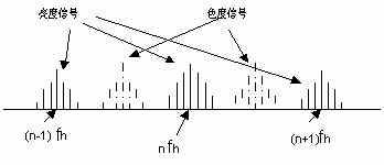
Fig. 07-03-4 Principle of spectral interleaving of luminance signal and chrominance signal
Another issue to consider when choosing fsc is that, as long as the chroma signal does not exceed the upper limit frequency of the Y signal, the value of fsc is selected as high as possible, as shown in Figure 07-03-5. Because the higher the fsc, the finer the spot of its interference with the Y signal, the lower the visibility. In addition, it is necessary to consider the beat interference between the secondary carrier frequency and the sound carrier frequency fs that may occur in the receiver. For this reason, the beat frequency between fsc and fs (fsc-fs) is also equal to an odd multiple of the half-line frequency to reduce the visibility of the interference point.
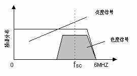
Figure 07-03-5 Luminance and chrominance signal spectrum of a common frequency band
Since there is only one subcarrier frequency, fsc, and the color difference signal as the modulation signal has two U and V, therefore, two phases of two different phases of the same carrier frequency need to be modulated. In the NTSC and PAL systems, the color difference signals U and V are modulated on two quadrature phases of the carrier frequency fsc, so it is called quadrature modulation.
The biggest problem caused by the transmission of bright and color signals in the same frequency band is the interference between the two. In order to reduce this interference, it is necessary to minimize the power of the color difference signal that does not carry information. The modulation method suppresses the carrier frequency component in the modulated wave, and the balanced amplitude modulated wave of the color difference signal after suppressing the carrier frequency can be expressed as:
![]()
In the frequency domain, the three signals of Y, U, and V are interleaved, while in the time domain, Y, U, and V are superimposed together, plus the signals finally formed by the various synchronization signals required to restore the image It is a full-color TV signal, and their bandwidth is the bandwidth occupied by the original black and white TV.
Medical Actuator
Medical series mainly apply for medical equipment, such as hospital bed, dental chair, rehabilitation training equipment, etc. They are very quiet so that you can barely notice it. More than 4 models are available for different requirements. Max. load ranges from 6,000N to 12,000N. There are different controllers to be chosen, including handset and control box.

Medical Care Actuator,Electric Linear Actuator,Actuator For Patient Lift,Dc Medical Care Actuator
TOMUU (DONGGUAN) ACTUATOR TECHNOLOGY CO., LTD. , http://www.tomuu.com