1, basic nouns: common basic topology

â– Buck Buck â– Boost Boost â– Buck-Boost Buck-Boost â– Flyback Flyback â– Forward Forward â– Two-Transistor Forward Dual Transistor Forward â– Push-Pull Push-Pull â– Half Bridge Half Bridge â– Full Bridge Full Bridge â– SEPIC
â– C'uk
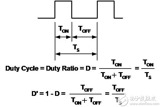
Basic Pulse Width Modulation Waveforms These topologies are related to switched circuits.
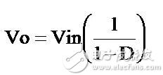
The basic pulse width modulation waveform is defined as follows:
2, Buck step down
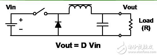
Features â– Reduce the input to a lower voltage.
â– Probably the simplest circuit.
â– The square wave after the inductor/capacitor filter filters the switch.
â– The output is always less than or equal to the input.
â– The input current is discontinuous (chopping).
â– The output current is smooth.
3, Boost boost
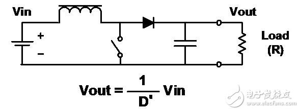
Features â– Raise the input to a higher voltage.
â– Same as buck, but rearranged inductors, switches, and diodes.
â– The output is always greater than or equal to the input (ignoring the forward voltage drop of the diode).
â– Input current is smooth.
â– The output current is discontinuous (chopping).
4, Buck-Boost buck-boost
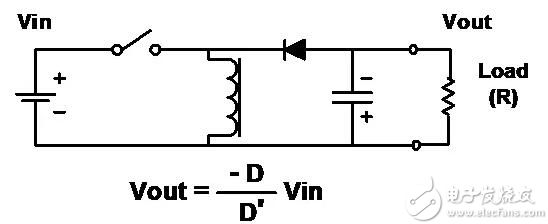
Features â– Another arrangement of inductors, switches and diodes.
â– Combines the disadvantages of buck and boost circuits.
â– The input current is discontinuous (chopping).
â– The output current is not continuous (chopping).
â– The output is always inverted from the input (note the polarity of the capacitor), but the amplitude can be less than or greater than the input.
■The “flyback†converter is actually in the form of buck-boost circuit isolation (transformer coupling).
5, Flyback Flyback
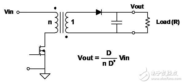
Features â– Works like a buck-boost circuit, but the inductor has two windings and acts as both a transformer and an inductor.
â– The output can be positive or negative, depending on the polarity of the coil and diode.
â– The output voltage can be greater or less than the input voltage, which is determined by the turns ratio of the transformer.
â– This is the simplest of the isolated topologies â– Increase the secondary windings and circuits to get multiple outputs.
6, Forward is excited
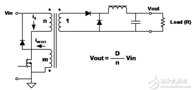
Features â– Transformer coupling form of the step-down circuit.
â– Discontinuous input current, smooth output current.
â– Because of the transformer, the output can be larger or smaller than the input and can be any polarity.
â– Adding multiple outputs can be achieved by adding secondary windings and circuits.
â– The transformer core must be demagnetized during each switching cycle. A common practice is to add a winding with the same number of turns as the primary winding.
â– The energy stored in the primary inductance during the switch-on phase is released by the additional windings and diodes during the switch-off phase.
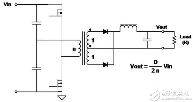
7, Two-Transistor Forward dual transistor forward
Features â– Two switches work at the same time.
â– When the switch is turned off, the energy stored in the transformer reverses the polarity of the primary and turns the diode on.
â– Main advantages:
â– The voltage on each switch never exceeds the input voltage.
â– There is no need to reset the winding track.
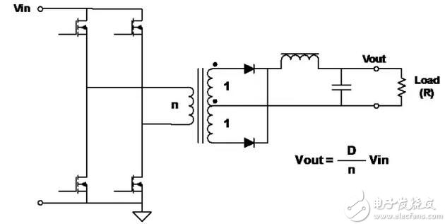
8, Push-Pull push-pull
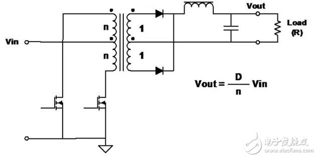
Features â– Switching (FET) drives out of phase and performs pulse width modulation (PWM) to regulate the output voltage.
â– Good transformer core utilization - transmitting power in both half cycles.
â– Full-wave topology, so the output ripple frequency is twice the frequency of the transformer.
â– The voltage applied to the FET is twice the input voltage.
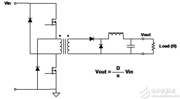
9, Half-Bridge Half Bridge
Features â– Very common topology for higher power converters.
â– The drive (FET) is driven out of phase and pulse width modulated (PWM) to regulate the output voltage.
â– Good transformer core utilization - transmitting power in both half cycles. Moreover, the utilization of the primary winding is better than that of the push-pull circuit.
â– Full-wave topology, so the output ripple frequency is twice the frequency of the transformer.
â– The voltage applied to the FET is equal to the input voltage.
10, Full-Bridge full bridge
Features â– The most common topology for higher power converters.
â– The switch (FET) is driven in a diagonal pair to perform pulse width modulation (PWM) to regulate the output voltage.
â– Good transformer core utilization - transmitting power in both half cycles.
â– Full-wave topology, so the output ripple frequency is twice the frequency of the transformer.
â– The voltage applied to the FETs is equal to the input voltage.
â– At a given power, the primary current is half of the half bridge.
11, SEPIC single-ended primary inductor converter
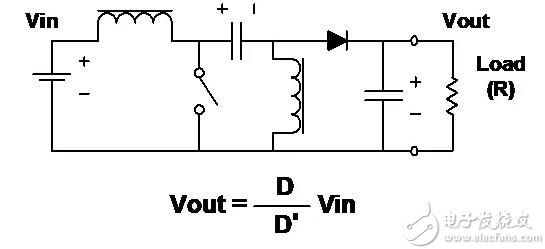
Features â– The output voltage can be greater or less than the input voltage.
â– As with the boost circuit, the input current is smooth, but the output current is not continuous.
â– Energy is transferred from the input to the output through a capacitor.
â– Two inductors are required.
12. C'uk (Slobodan C'uk patent)
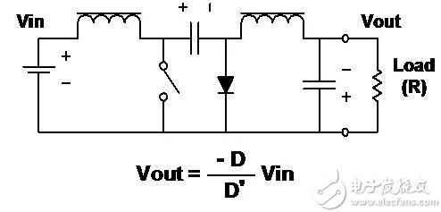
Features â– Output inversion â– The amplitude of the output voltage can be greater or less than the input.
â– Both the input current and the output current are smooth.
â– Energy is transferred from the input to the output through a capacitor.
â– Two inductors are required.
â– The inductor can be coupled to obtain a zero ripple inductor current.
13, the details of the circuit work The following explains the working details of several topologies â– Buck regulator:
Continuous Conductivity Critical Conduction Discontinuous Conduction â– Boost Regulator (Continuous Conduction)
â– Transformer operation â– Flyback transformer â– Forward transformer 14. Buck-buck regulator - continuous conduction
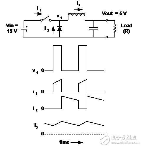
â– Inductor current is continuous.
â– Vout is the average of its input voltage (V1).
â– The output voltage is the input voltage multiplied by the duty ratio (D) of the switch.
â– When connected, the inductor current flows out of the battery.
â– Current flows through the diode when the switch is turned off.
â– Ignore losses in switches and inductors, D is independent of load current.
â– The characteristics of the buck regulator and its derived circuit are:
The input current is discontinuous (chopping) and the output current is continuous (smooth).
15, Buck-buck regulator - critical conduction
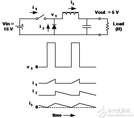
■The inductor current is still continuous, but “reaches†zero when the switch is turned back on.
This is called "critical conduction."
The output voltage is still equal to the input voltage multiplied by D.
16, Buck-buck regulator - discontinuous conduction
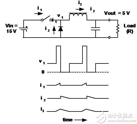
â– In this case, the current in the inductor is zero for a period of time in each cycle.
â– The output voltage is still (always) the average of v1.
â– The output voltage is not the input voltage multiplied by the duty ratio of the switch (D).
â– When the load current is below the threshold, D varies with the load current (while Vout remains the same).
17, Boost boost regulator
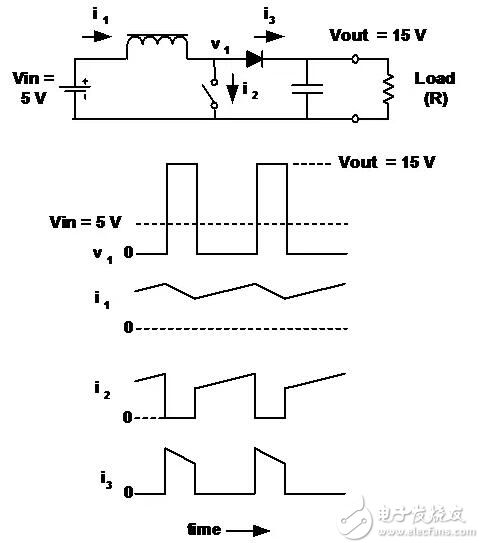
â– The output voltage is always greater than (or equal to) the input voltage.
â– The input current is continuous and the output current is discontinuous (as opposed to the buck regulator).
â– The relationship between output voltage and duty ratio (D) is not as simple as in a buck regulator. In the case of continuous conduction:
In this case, Vin = 5,
Vout = 15, and D = 2/3.
Vout = 15, D = 2/3.
18, transformer work (including the role of the primary inductance)
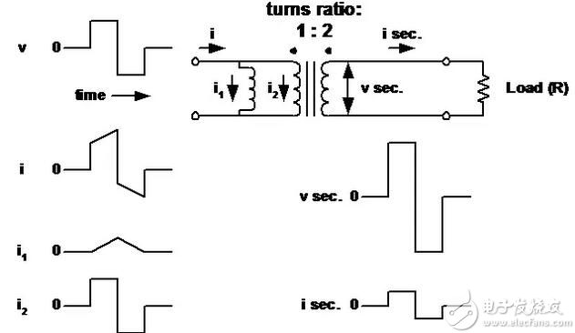
â– The transformer is considered an ideal transformer with its primary (magnetized) inductance in parallel with the primary.
19. Flyback transformer
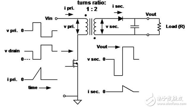
â– The primary inductance is low here and is used to determine the peak current and stored energy. When the primary switch is turned off, energy is transferred to the secondary.
20, Forward forward conversion transformer
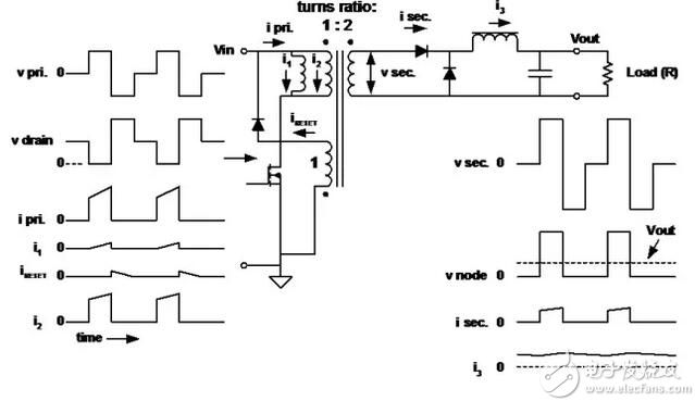
â– The primary inductance is high because there is no need to store energy.
â– The magnetizing current (i1) flows into the “magnetizing inductorâ€, causing the core to demagnetize after the primary switch is turned off (voltage reversal).
21. Summary â– This review of the most common circuit topology in switching power supply conversion.
â– There are many topologies, but most are combinations or variations of the topologies described here.
â– Each topology contains unique design trade-offs:
Voltage applied to the switch Chopping and smoothing the input and output current Winding utilization â– Choosing the best topology requires research:
Input and output voltage range Current range Cost to performance, size and weight ratio
Magnetic USB Cable refers to the magnet male and female to suction mode to connect the charging effect of the charging cable. Rely on the magnet magnetic attraction, traditional cable connector is separated from the cable body, both through magnetic in automatic adsorption within a certain distance, so called magnetic suction cable magnetic suction cable, magnetic suction cable, magnetic suction charging cable, etc.so that we can realize single hand plug cable, and in the process of actual use, the magnetic suction charging cable is safer than ordinary USB Cable.
Interface widely applicable to mainstream models.Thin small size for wide, differs from the traditional life of the common data interface,a new type of magnetic suction cable charging interface on the size of the thin body, even mobile phones with a set of use, magnetic suction cable also apply to the charging 90% of cell phone sets, don't need to pick a set can be used directly, so it is suitable for use in the increasingly miniaturization of electronic equipment, Can withstand more than 50,000 times of repeated insertion and removal. Fast transmission speed, perfectly compatible with mobile phone data transmission.
It is easy to use,can be single-hand operation,regardless of positive and negative, random insertion, the error rate is zero, even if the 3-year-old children can not be inserted wrong, very suitable for driving, sleeping and other life scenarios. The appearance of magnetic charging cable has impacted the market of Usb C Cable, because magnetic charging cable is much better than ordinary data cable, bringing too much convenience to life. The feeling of user experience has also risen, and more people begin to enjoy the sense of convenience brought by magnetic charging cable to life.

Magnetic Usb Cable,5A Usb Cable,Magnetic Micro Usb Cable,Led Magnetic Charging Cable
Henan Yijiao Trading Co., Ltd , https://www.yjusbhubs.com