The electrical control system consists of an electric motor and various control appliances (such as contactors, relays, resistors, switches, etc.). A diagram reflecting the connection relationship of each electrical component in the electrical control system is referred to as an electrical control system diagram. Electrical control system diagrams include electrical schematics, electrical layouts, and electrical installation diagrams. This section only describes electrical schematics.
The circuit diagram drawn by the principle of the main circuit and the auxiliary circuit by the prescribed graphic symbols and text symbols, and drawn according to the principle of the operation order of each electrical component is called an electrical schematic. For the convenience of design, research and analysis, installation and maintenance, the electrical schematic symbols and text symbols specified by the state must be used when drawing the electrical schematic. Graphical symbols refer to graphical symbols of motors, appliances, and components. Textual symbols indicate the names, uses, and characteristics of motors, appliances, and components represented by graphical symbols.
In order to facilitate the reading and analysis of the control circuit, the electrical schematic is generally drawn in the form of an electrical component expansion. It includes the conductive parts and wiring ends of all electrical components.
The schematic drawing and precautions of the electrical schematic are now described with the electrical schematic of the CW6132 horizontal lathe shown in Figure 1.
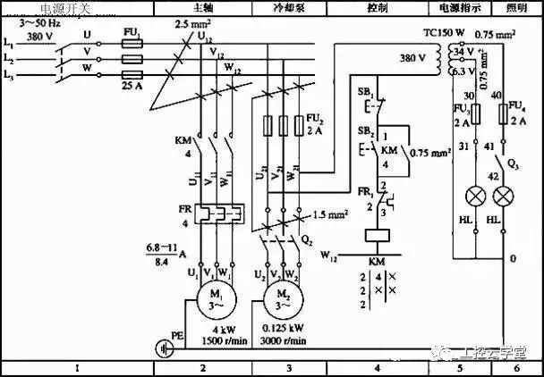
Figure 1 Electrical schematic of the CW6132 lathe
1 Principles to follow when drawing electrical schematics(1) The main circuit label consists of a text symbol and a number. The text symbol indicates the main features of the electrical component or line segment in the main circuit, and the different line segments of the digital difference circuit, such as UVW, U1V1W1 and U2V2W2 in the figure.
(2) The control circuit is numbered in Arabic numerals and consists of three or fewer digits. In the vertically drawn circuit, the label order is numbered from top to bottom and from left to right. Any line segment separated by coils, windings, contacts or resistors, capacitors, etc., should be marked with different circuit numbers.
(3) From the power supply to the motor circuit, the current passing through is large, called the main circuit, drawn with thick lines; the auxiliary circuit (including the control circuit, the lighting circuit, and the signal circuit) has a small current and is drawn with thin lines.
(4) Regardless of whether it is a main circuit or an auxiliary circuit, each electrical component is arranged in order from top to bottom and left to right in order of motion, and may be vertically arranged or horizontally arranged.
(5) Mark the voltage value, polarity, frequency, and number of phases of each power supply circuit.
(6) The contacts of the relay and the contactor are drawn according to the state in which the attracting coil is not energized, and the contacts of the button and the stroke switch are drawn in a state where they are not subjected to an external force.
(7) The conductive parts of the same appliance (such as relays, coils and contacts of contactors) are drawn separately according to their relationship in the circuit, but are represented by the same text symbols. For several appliances that perform the same function, the number is added to the lower right corner of the same text symbol to indicate the difference.
(8) The power circuit of the power circuit is drawn into a horizontal line, and the motor and its protective electrical circuit are drawn as vertical lines; the auxiliary circuit is vertically drawn between two or several horizontal power lines, coils, electromagnets, illumination lights, signal lights The indicator light is connected to the grounded horizontal power line, and the control contact is connected to another power line.
(9) Cross-wire connection points with direct electrical contact must be indicated by black dots, otherwise black dots are not drawn.
2 division of the map areaDivide the picture into several picture areas above the schematic and indicate the purpose and function of the circuit in the area. The 1, 2, 3, ... numbers below the schematic are the area numbers, which are set up for easy retrieval of electrical wiring and easy reading analysis.
3 index of the corresponding position of the coil and contactor of the relay and contactorA contact table is arranged below the relay and the contactor coil, indicating the area number of the contact corresponding to the coil. Below the contactor KM coil, the first column from left to right indicates the area number of the normally open main contact, the second column indicates the area number of the auxiliary normally open contact, and the third column indicates the area number of the normally closed auxiliary contact.
The first column from left to right of the intermediate relay and current relay KA coil indicates the area number of the normally open contact, and the second column indicates the area number of the normally closed contact.
The first column from left to right of the time relay KT coil is marked with the area number of the time-delay normally open contact, the second column is marked with the area number of the normally closed contact, and the third column is marked with the area number of the momentary normally open contact. The fourth column indicates the area number of the momentary normally closed contact.
Mark the area number of the coil corresponding to the contact under the contacts of the relay and contactor.
4 technical data annotationTechnical data of each electrical component should also be marked in the electrical schematic diagram, such as the rated current of the fuse melt, the operating current range of the thermal relay and its setting value, and the cross-sectional area of ​​the conductor.
Breadboard And Wire Kit,Breadboard Starter Kit,Electronic Breadboard Kit,Breadboard Jumper Wire Kit
Cixi Zhongyi Electronics Factory , https://www.cx-zhongyi.com