An open robot controller was developed for the problem of how robot dynamic compliance control is implemented in engineering. This controller adopts the control structure of "PC+PMAC". By using two different control modes of servo drive, a practical force/bit hybrid control scheme is proposed, and the corresponding hardware and software implementation is given. Experiments show that the force/bit hybrid control method proposed in the paper has good stability and force control accuracy.
1 IntroductionWith the increasing use of robots in various fields, many occasions require robots to have force control capabilities. For example, precision assembly of robots, shaving or surface grinding of workpieces, polishing and scrubbing. It is required to keep the end effector in contact with the environment during operation. To complete these tasks, you must have the ability to control the force from free space to constraint space.
The compliance control is divided into active compliance control and passive compliance control. Passive compliance control has limited application due to its high professionalism and low success rate. In order to overcome its shortcomings, it is necessary to adopt active compliance control, that is, force control. The system adopts an open robot controller based on PC bus. The structure of PC+DSP motion control card is used to construct an open hardware platform of special robots to meet the needs of robots in controlling contact force.
2, the working principle of the force/bit hybrid control special robotFor special contact work, the robot in this system is a flat three-degree-of-freedom operator, and the entire operator has one moving pair and two rotating pairs. It is suitable for completing some contact work in the inner or outer wall surface of the rotary housing, such as cleaning dirt or grinding the surface in the housing. Among them, the whole operator is driven by three servo motors, and the rotary housing is driven by a servo motor, and a total of four servo motors.
3, the composition of the open robot controller3.1 Implementation mode of open robot controller
The control system is: I: Industry Control Computer (IPC) is the upper computer, and the DSP control card plugged into the ISA expansion slot of the IPC motherboard is the control core of the system. The control mode of the IPC+PMAC dual CPU has the characteristics of convenient implementation, powerful function and high reliability, and is an open control system. The entire controller adopts a modular architecture, the industrial PC handles the non-real-time part, and the real-time motion control is undertaken by the DSP motion control card.
The DSP motion controller used in the control system is Delta Tan's Type I PMAC eight-axis motion control card. PMAC demonstrates excellent open performance and powerful motion control capabilities both in hardware and software. Compared with general motion controllers, PMAC cards have strong processing power, trajectory characteristics and input bandwidth, and have strong flexibility, which can be applied to multi-bus structures (PC, STD, VME).
Its specific functions include: multi-axis interpolation calculation, user-assisted PLC programming, and analog data acquisition and processing. The hardware core of the PMAC control card in this system is Mo. Tomla's DSP56003 digital signal processing chip, servo cycle single axis is 55Vs, can receive a variety of feedback signals from tachogenerators, photoelectric encoders, gratings, resolvers, and can be compatible with a variety of servo motors. The excellent characteristics of the PMAC control card provide a good hardware platform for implementing dedicated robot force control.
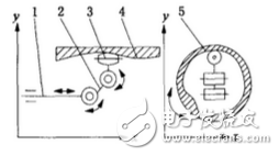
Figure 1 robot operating hand working principle diagram
1. Big arm 2. Arm 3. Actuator (can be rotated around the X axis) 4. Irregular inner wall surface 5. Slewing housing
The I type PMAC used in this system has an external interface with different functions of j1 - J8, and can control 1 to 8 axes. Four interfaces are used in this system. J3 (multiple DIP switch I/0) is connected to ACC-34AA (accessory to PMAC); J5 (general digital input and output) is a control optocoupler and intermediate relay; J7 ( Analog output 5-8 axis) A control actuator and drive rotary housing; J8 (analog output 1-4 axis) - control boom and arm motor.
3.2 The hardware platform of the film sticking robot
This system uses IPC, PMAC I type 8-axis motion control card, dual-port RAM (DPRAM), I/O expansion board ACC-34AA, Panasonic, Yaskawa servo motor and driver for a total of four sets. One interface board. The control system is shown in Figure 2. The interface connection board developed by the system is shown in Figure 3.
In the control system, two attachments to the PMAC are used:
1DPRAM (Dual port RAM): Dual port RAM
2ACC-34AA: Multi-channel I/O driver board
Among them, DPRAM is an attachment to PMAC and is a communication bridge between IPC and PMAC. DPRAM can share high-speed memory area between host and PMAC. It can easily exchange hands-free data through DPRAM, 1PC and PMAC. The DPRAM has an address mapping between the host (IPC) and the PMAC. This address mapping matches the memory of both sides of the memory II: DPRAM guarantees the real-time performance of the data, which improves the sensitivity of the control system and enables the operator to implement active compliance control. The force error is reduced and the force control accuracy is greatly increased. The relationship between DPRAM and IPC and PMAC is shown in Figure 4.
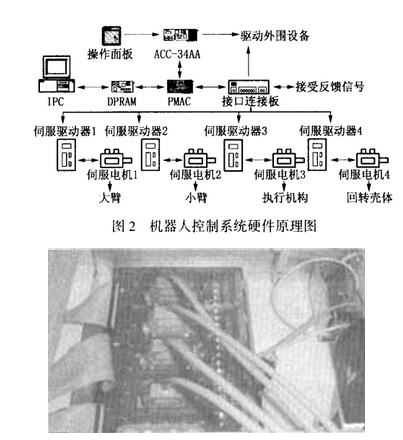
Figure 3 wiring connection board outline drawing
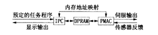
Figure 4 DPRAM connection diagram
The ACC-34AA is also an accessory to the PMAC. It provides 64 optically isolated discrete I/() points, grouped in 32-bit words, with 32 input points and 32 output points. The input point can receive an external input control signal for the PMAC to make a decision. For example, the input control signal of the control panel 1: is accepted in the system.
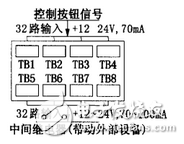
Figure 5 ACC-34AA basic function diagram
The output point can be connected to the relay component, and finally controls the start and stop of the peripheral device. The basic functions of the ACC-34AA are shown in Figure 5.
After the PMAC is run, the PIc program reads and writes only the ACC-34AA input and output through the M variable.
4 Force/bit mixing control of open special robot4.1 The necessity of force control
In order to make the robot flexible in a constrained environment while avoiding excessive contact force or moment when in contact with the environment, the robot terminal is required to have the ability to simultaneously control its terminal position and force. In this system, the robot operator performs predetermined contact work in a rotating housing with a small working space. This operation requires the actuator to be accurately positioned on the inner wall of the housing while being able to be on the inner wall surface of the irregular rotating housing. Different areas are always in contact and the contact force is constant or output as specified. Therefore, this paper considers force control on the basis of the position servo system, so that the operator can obtain flexibility to the unknown environment.
4.2 Hardware implementation based on PMAC force/bit hybrid control
In order to achieve the force/bit mixing control at the end of the robot, the analog output of the PMAc is required to operate in the speed and torque control mode of the servo drive, as shown in Figure 6.
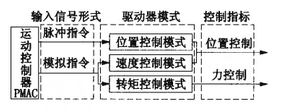
Figure 6 servo drive output mode
Both the speed mode and the torque mode of the drive accept analog signals from the host controller (PMAC). Among them, the speed mode is based on the control position as the main control index, while the torque mode is based on the control torque as the main control index. In the torque mode, the constant torque output can be realized within the rated torque range.
In order to achieve the above requirements, the contact operation of the operator is divided into three steps: first, the operator reaches the predetermined position in the speed mode and maintains a certain posture, and the position control using the current loop is more accurate in this mode; The motor performs mode switching, and the arm is lifted vertically in the torque mode. When the actuator approaches the housing, the motor of the actuator is in a free state to ensure good attachment to the inner wall of the housing; finally, in the end mechanism and the housing When the wall is in contact, the housing rotates, and the feedback information is used to adjust the torque of the arm servo motor so that the actuator can always keep in contact with the housing and control a certain contact force, thereby enabling the robot to perform effective force control under the unstructured surface. , complete contact work.
In this system, the PMAC motion controller controls the four-axis linkage, but since the boom, arm and actuator in the operation are operated in two different modes, the number of axis channels actually occupying the PMAC is seven. In these two modes, the input side of the driver side accepting the controller command is different. For example, the Panasonic driver is used. In the speed mode, the 14 and 15 pins are used, and in the torque mode, the 16 and 17 pins are used. The two-channel connection between PMAC and drive mode conversion in this system is shown in Figure 7.
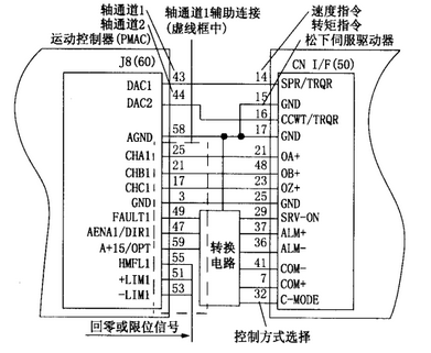
Figure 7 Dual-axis channel servo output connection diagram
The analog outputs of the two axis channels DAC1-DAC2 (PMAC's 43, 44) shown in Figure 7 are connected to the servo drive's speed and torque command pins (14, 16 on the driver side). The auxiliary connection of axis channel 1 (DAC1) refers to the connection related to feedback, driver enable and error, limit and so on. For example, CHAl-CHCl is the encoder disk feedback signal of channel 1, +LIMI and a LIMl are the limit signals in the reverse direction and the positive direction, AENAI/D1RI is the amplifier enable signal, which determines the enable of the servo driver, and other similar references. The foot is not detailed. PMAC's J8 has 60 pins, and there are four axis outputs {channels. Each axis output channel has a similar set of auxiliary connections. Each axis output channel is out of analog output according to its corresponding auxiliary connection, and the servo is completed. Features. On the driver side, to implement two modes, the analog command signal of the axis output channel needs to be switched between 14 and 16. If an axis output channel is used, it is necessary to build a circuit between the PMAC and the driver to complete the switch. This is not good in real time and reliability is not high. Therefore, the system uses the two axis channels of PMAC to realize the servo output of the two modes of the 埘 drive, so that it is not necessary to build an external circuit, and 11 guarantees the real-time requirement. The specific method is to change the state of C-MODE through J5 1 of PMAC. If two axis channels are controlled separately, two sets of auxiliary connections are required to ensure the servo output of the axis channels, but in fact one driver and the external switch can only provide one set of axis channel auxiliary connections, which requires the PMAC to complete the output switching within it. By setting the IX0217 J in the I variable, this switching guarantees that the PMAC will servo output to the two axis channels on the premise that there is only one set of axis auxiliary connections.
4.3 Software implementation based on PMAC force/bit control
The entire control software includes two parts: real-time control software and system management software of the host computer. Real-time control software includes servo drive, PLC monitoring, data acquisition, etc.; system management software includes initialization, parameter input, dual CPU communication, shell operation planning, etc. In order to realize the force/bit mixing control of the operating hand in PMA (:, the control software writes the system application in VC++6.0 on the Windows platform L, and simultaneously calls the function in the PCOMM32PRO dynamic connection library in PMAC to complete the real-time operation of PMAC. operating.,
Make the following settings and definitions in the PMAC initialization procedure:
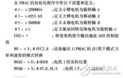
Where P1 is the abscissa of the position of the entrance of the casing, P2 is the abscissa of the working position of the casing, P3 is the ordinate of the working position of the casing, and P]00 is the torque setting value. /102 is the motor command output address, 1169 is the arm motor DAC output limit, and c is the index arm angle limit. M162 stores the actual position value of the arm motor (motor 1) in the register. M168 is the output torque to the DAC calibration value.
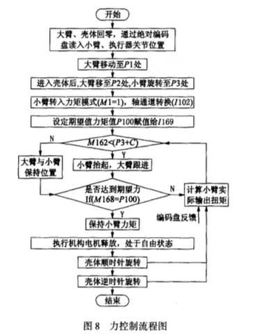
The control flow is shown in Figure 8.
5 ConclusionThis paper studies a practical open robot controller for special robots that need to complete contact work. Applying the open structure of IPC and PMAC dual CPU, it realizes two levels of openness, obtains better human-computer interaction ability, and on the basis of the effective force/bit mixing control of the robot, gives specific Controlled hardware and software implementation that enables the robot to perform contact operations on unstructured surfaces. The system has achieved good control effects in the patching operation for the inner wall surface of the irregular casing.
Cold-resistant Network Cable include CAT5E cold-resistant network cable, cat6 cold-resistant network cable, cat7 cold-resistant network cable.Cold-resistant network cables support the transmission frequency and the Channel Bandwith are same as the normal network cables.
The difference between the cold-resistant network cable and the normal network cable is the cold-resistant network cables can operate in temperatures of minus 40 degrees.
Cold-Resistant Network Cable,Cold-Resistant Corrosion-Resistant Spring Network Cable,Wire Electric Cable,Electric Wire
Shenzhen Kingwire Electronics Co., Ltd. , https://www.kingwires.com