Entering the practical stage of electromagnetic induction
This article refers to the address: http://
Among the above three methods, the wireless power supply system using the company's electromagnetic induction method has entered the empirical stage. It is scheduled to be imported into the actual bus line after the fall of 2011. In this sense, it can be considered that the wireless power supply method that can be immediately put into practical use is only an electromagnetic induction method.
The electromagnetic induction method will be described in detail below. The electromagnetic induction method can basically be considered as one type of transformer (Fig. 4). That is to say, similar to when the gap between the core and the core is zero, a transformer with a frequency of 50 Hz is output after input at a frequency of 50 Hz.
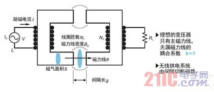
Figure 4: Same as the transformer
Non-contact charging is similar to a transformer with a large gap.
If it is an ideal transformer, the magnetic flux will not leak because the gap is very small, so the coupling coefficient (k) is basically 1. However, a certain gap is required for wireless power supply, so magnetic lines of force are leaked. Therefore, k will be less than one.
The static circuit in which the primary coil and the secondary coil are opposite each other is in principle provided with an inverter in any case, from the inverter receiving power in the secondary coil via the primary coil, and then connected to the load (RL) (Fig. 5). Of course, it can also be converted to DC, but it needs to be rectified.
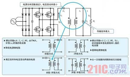
Figure 5: Need to use capacitors for resonance
The static electromagnetic induction method requires a capacitor to resonate in order to improve the transmission efficiency.
However, the efficiency of the coil alone cannot be improved. The optimum load (ZL) that maximizes transmission efficiency is expressed by ZL = RL - jωL. From this equation, it is known that there is a negative reactance on the rear side of the RL, and therefore a resonance portion based on the capacitance component is required. Therefore, whether the capacitor is mounted in series or in parallel, resonance is obtained by the capacitance component of the capacitor.
Further, in order to prevent the fluctuation of the secondary coil from adversely affecting the voltage fluctuation rate of the primary coil, a capacitor is often mounted in the primary coil portion to increase the power factor of the system. So where is the capacitor installed? This article will list about nine installation examples, and specifically describe the four representative ones.
When the value of k is large, the mutual inductance M is also large. As shown in the "/series mode" of FIG. 5, a series capacitor for compensating for magnetic flux leakage may be disposed only in the secondary coil. When the value of k is small, as shown in the "/parallel method", a capacitor having a resonance frequency of the secondary side self-inductance as a power source frequency is arranged in parallel in the secondary coil portion.
In order to improve the power factor of the power supply, the series capacitors are generally arranged on the primary side as in the "series/parallel mode", but sometimes they are configured to be used from the primary coil to the air gap (Air Gap) as in the "parallel/parallel" mode. A shunt capacitor that provides reactive excitation.
In fact, in the electromagnetic induction mode, the transmission efficiency (η) between the coils of the magnetic resonance method is proportional to the square (α) of the product of the coupling coefficient (k) and the resonance peak (Q) (Fig. 6). Our 30kW electromagnetic induction method has an efficiency of about 92% between coils when α is about 103.
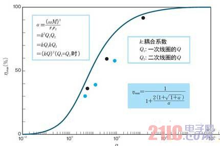
Figure 6: Transmission efficiency proportional to α
In the electromagnetic induction mode, the transmission efficiency η between the coils of the magnetic resonance mode is proportional to the square α of the kQ product. The black point is the electromagnetic induction method and the blue point is the experimental result of the magnetic resonance method.
We are still developing magnetic resonance methods and have reached the black point level of Figure 6. At this level, even if the distance is about 60 cm to 1 m, the efficiency between the coils can be improved by about 60% by increasing the Q value.
Debut in the 1980s
Cars have a long history, and in fact EVs appear earlier than engines. As early as the dawn of the car, there was a time when EV was popular. After that, EV gradually withdrew from the historical stage due to the convenience of gasoline, but recently, the era of EV is finally expected to return to the stage.
The wireless power supply for cars was born in the 1980s. At that time, small inverters with cheap prices appeared, and wireless power supply development was on the right track. In 1995, the PSA Peugeot Citroen Group implemented the “Transport Urbain (Individuel et Public)†program in France using electromagnetic induction, which is the prototype of our wireless power supply system. The system sets a primary coil on the ground. After the car with the secondary coil below the local board stops on the primary coil, information is exchanged between the primary side and the secondary side, and the amount of charge is controlled according to the power required by the vehicle. At that time, the output power was small, 6 kW.
A wireless power supply system capable of transmitting power at a higher output power is Wampfler's "IPT (Inductive Power Transfer)". At present, dozens of units have been imported overseas, and four units have been introduced in Japan. The principle is the same as the Tulip program, but the output power can reach 30kW. Stefler has developed a system that communicates with the BMS (Battery Management System) that allows the vehicle's battery to reach its optimal state of charge to obtain the value required for charging. The IPT is equipped on the bus. When the passengers at the bus station get on and off the vehicle, the charging is completed from the lower side of the vehicle. It can be said that the current practice of the basic concept of wireless power supply for electric buses.
Japan is also beginning an empirical test
With the assistance of NEDO, Showa Aircraft Industry manufactured the WEB-1 (Waseda Electric micro Bus 1) mini electric bus for Waseda University in 2004 and equipped it with the IPT of Stefler (Figure 7). The vehicle battery adopts the "ZEBRA Battery" of the Swiss MESSEA salt-melting salt battery, and then changed to the lithium-ion rechargeable battery, but both of them have the problem of high battery cost.
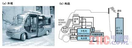
Figure 7: Mini electric bus "WEB-1" with wireless power supply system
WEB-1's original contactless power supply system uses the IPT of the company, the battery is equipped with sodium molten salt batteries and capacitors, and later changed to the self-developed wireless power supply system and lithium-ion rechargeable battery.
Therefore, we have reduced the weight of the vehicle while reducing the initial introduction cost by minimizing the battery capacity, thereby improving fuel efficiency. However, after the battery capacity is reduced, the driving distance for charging once is shortened. Therefore, the battery is not fully charged only at the terminal station and the station, but is charged in a short time for the basic mode.
IPT's test results at Waseda University's Honjo campus show that even battery capacity can be used. In particular, the CO2 emission reduction effect is very large.
However, wireless power supply systems produced overseas have many problems such as large size, high price, and inability to ensure large gaps. Therefore, in 2005-2008, with the assistance of NEDO, we started to work on the localization of wireless power supply systems.
Sensor Trash Can,Foot Sensor Automatic Dustbin,Foot Sensor Dustbin,Foot Sensor Trash Can
NINGBO ZIXING ELECTRONIC CO.,LTD. , https://www.zixingautobin.com