With the development of highway transportation, the speed and circulation density of vehicles have been greatly improved, but traffic accidents have also occurred frequently. How to reduce traffic accidents has become a top priority, which puts new demands on car safety technology. Safety and intelligence will become the most important development trend of new automotive safety technologies in the future. More attention will be paid to active safety technology, which is to prevent accidents. Specifically, attention is paid to each subtle link such as detection of oil pressure, air pressure and temperature, and it is possible to promptly and conveniently inform the driver of the abnormal situation, thereby minimizing the safety hazard. To this end, this article will introduce a car safety alarm, which can automatically detect vehicle system parameters such as temperature, pressure, and vehicle speed, and issue a voice alarm when abnormal conditions occur. The system is low in production cost, small in size, high in safety, easy to install, clear in voice, and suitable for general automobile use.
This article refers to the address: http://
First, the overall plan
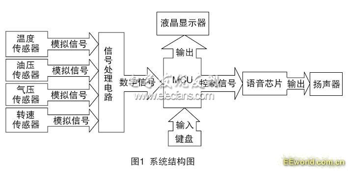
As shown in Figure 1, the system consists mainly of a detection subsystem, an alarm subsystem, a display subsystem, and a voice subsystem. The detection subsystem consists of a number of sensors, each of which forms a parameter detection system and inputs this value to the main controller. The temperature detection sub-module uses the DS18B20 sensor. The vehicle speed detection and pressure detection can use suitable sensors to facilitate signal acquisition of the controller. The AT89C52 single-chip microcomputer is used as the main controller, and the voice chip uses WT588D as the output device of the voice alarm. The 4×4 matrix keyboard and LCD12232 provide the human-machine interface, which is convenient for parameter setting and setting of the system. In addition, a clock system is installed in the system to effectively record the real-time parameters of the vehicle system. These parameters can be queried by pressing the button. After setting the parameters of the system, the system enters the working state. Taking temperature monitoring as an example, the main controller periodically scans the sensor interface for alarm signal collection. The main controller processes the detection signal of the DS18B20 and the alarm value set by the system to determine whether the value satisfies the alarm condition. The main parameters can be displayed in real time on the human interface LCD to increase its reliability. The system may have to judge the alarm level corresponding to the measured value, and issue a control command to the voice system according to this, and output the alarm information in the form of sound and light, which is convenient for the user to handle in time. The same monitoring mechanism is also applied to other parameters of the vehicle body. As an embodiment of intelligence and humanization, the system can independently input alarm prompt voices and select different voice service modes. For each parameter, you can play its personalized voice prompts, so that you can quickly find the cause of the alarm in the alarm. For the important level of a certain parameter, the loop play mode and the single play mode can be selected separately. You can press the button to query the real-time information, alarm information and alarm times and times of different parameters.
Second, the system hardware design
The system hardware circuit is mainly composed of three parts: signal acquisition and processing module, voice module and keyboard display module. Using AT89C52 MCU as the main controller, using WT588D voice module as voice prompt
1. The signal acquisition and processing module system uses the DS18B20 to detect temperature parameters at important locations of the vehicle body, such as oil temperature and temperature near important axles. The signals of the plurality of temperature sensors are read by the controller in a chip select manner. The signal from the pressure sensor also requires a dedicated processing chip for preliminary processing of the signal. The hardware connection of the signal acquisition and processing module is shown in Figure 2.
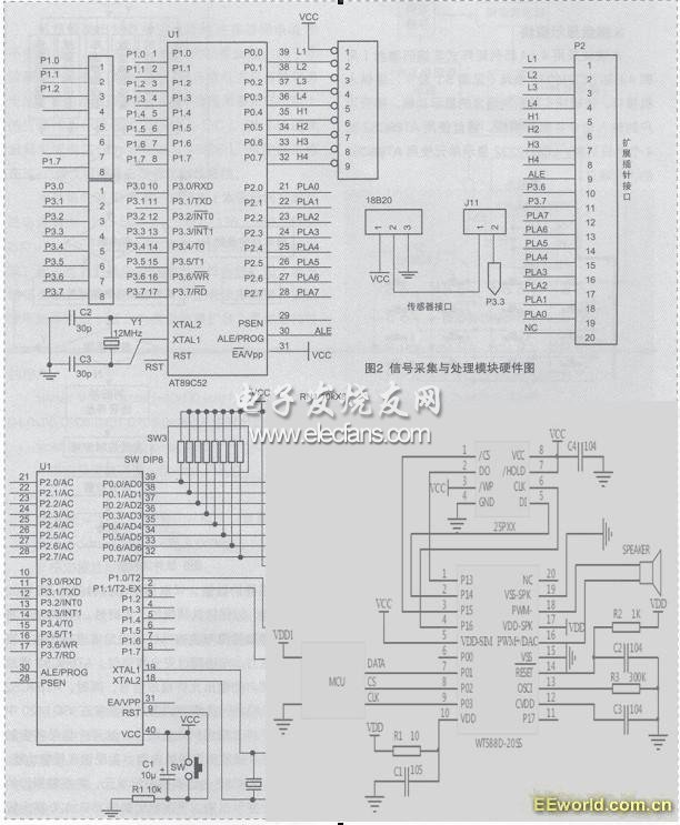
2. Voice recording and playback module
The voice module hardware consists of WT588D chip, AT89C52 control line, memory by SPI flash and WT588D master control and alarm voice output device (horn), as shown in Figure 3. The WT588D chip is the core part of this module and accepts control commands and has a vertical memory unit. WT588D can be repeatedly erased and played for a long time. It is very convenient for developers. It is a very good voice circuit because it solves the problems of OTP for short time, expensive and can't be repeated. WT588D master can plug in 2-32M SPI flash, the price between OTP and MP3, and can be downloaded repeatedly, you can take the chip solution.

3. Keyboard display module
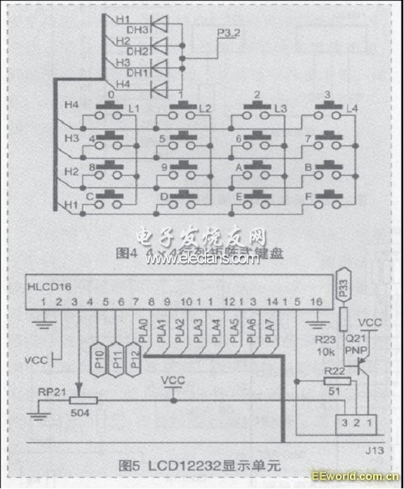
This module uses a 4 × 4 matrix matrix non-coding keyboard (see Figure 4) and LCD12232 unit (see Figure 5) display, providing a human-machine interface. The module implements the display function of the system information, accepts the user's input command and responds. The keyboard uses the four peripheral pins of the AT89C52. The LCD12232 display unit uses one port of the AT89C52.
Third, system software design
According to the above analysis and hardware schematic diagram, the main task of the software design is to compare and judge the value of the temperature or pressure sensor and the user's set value, and control the voice chip to perform the alarm. The software flow is shown in Figure 6. The MCU periodically reads the values ​​of the temperature sensor DS18B20 and other sensors. The read cycle is controlled by the clock chip DS1302 to ensure its accuracy and real-time performance. The AT89C52 compares the measured values ​​of the sensors with the setpoints of the monitoring system. When the temperature or pressure and the vehicle speed exceed the safety threshold, the AT89C52 playback control pin automatically outputs the allowable playback signal. At the same time, the AT89C52 also looks up the voice prompt to record the address in the WT588D according to the type of danger and output it to the address line. Two signals will trigger the voice chip to play the specified segment of the content to achieve a voice alarm function. At the same time, the AT89C52 will also wake up the display unit and display the details of the cause of the alarm. Given below is the WT588D routine
Description: This program is a test program. Please change the MCU IO port according to the actual application.
#include
Sbit KEY=P1^1; /*P1_1 is the second digit of port P1*/
Sbit CS=P3^1; /*P3_1 is the third digit of port P3*/
Sbit SCL=P3^2; /*P3_2 is the 4th digit of port P3*/
Sbit SDA=P3^0; /*P3_0 is the 5th bit of P3*/
//sbit DENG=P3^7; /*P3_5 is the 6th bit of P3*/
Void delay1ms(unsigned char count) //1MS delay subroutine
{
Unsigned char i,j,k ;
For(k=count;k>0;k--)
For(i=2;i>0;i--)
For( j=248;j>0;j--);
}
Void delay100us(void) //100US delay subroutine
{
Unsigned char j;
For( j=50;j>0;j--);
}
Send_threelines(unsigned char addr) //Three-line code subroutine
{unsigned char i;
CS=0;
Delay1ms(5);
For(i=0;i<8;i++)
{SCL=0;
If(addr & 1)SDA=1;
Else SDA=0;
Addr>>=1;
Delay300us(); /* 300us */
SCL=1;
Delay300us();
}
CS=1;
}
Main()
{unsigned char FD=0;
P3=0XFF;
While(1)
{
If(KEY==0)
{
Delay1ms(20);
If(KEY==0) //Increase the code value by pressing the button P1.1
{
Send_threelines(FD);
FD++;
If (FD==220// three-wire serial port, the voice segment is temporarily up to 220 segments
{
FD=0;
}
While(KEY==0); //Wait for the button to be released, so as not to make a few mistakes
}
}
}
Engineers can choose addresses based on actual needs.
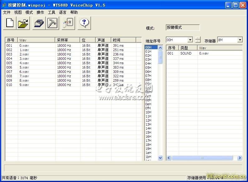
Download the sound and download the software is very simple and convenient.
Just put the sound to the corresponding address location to display the cause of the alarm
During the use of the system, the user may view or modify the setting information of the system or modify the working mode of the alarm according to actual needs. It is more important to modify the parameters of the alarm system during the testing process. The matrix keyboard implements this functionality. The MCU reads the input of the keyboard in an interrupted manner, accepts the user's setting command, and implements the voice monitoring function.
Fourth, summary
The actual test and use prove that the system is simple, convenient and practical, stable in operation, high in reliability and low in cost. In addition to the special protection of sensors and lines in special locations, the system does not take up extra space and has good compatibility with existing systems. The promotion of the system in the automotive system will effectively improve the safety of the automotive system.
It is the cover of the Cable Tray.It is compacted by steel or fiberglass plate material.Our Cable Tray Cover has high strength and can protect cable from dust or corrosive things.
Cable tray cover has higher intensity steel strength due to the concave convex surface shape structure.
Due to the benefits from the increase of steel strength,thinner material could be used.
Good point is that we can lower cost and the product is not easily deformed.

Cable Tray Cover
Cable Tray Cover,Perforated Cable Tray Cover,Covers For Cable Trays,Cable Tray Trunking With Cover
Jiangsu Loncin Electrical Equipment Co.,Ltd , https://www.loncincabletray.com