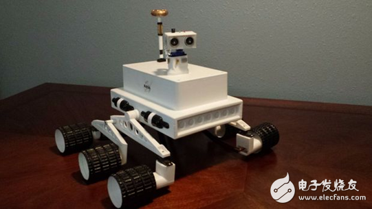
This production covers all the steps of making a lunar rover, including: the construction of STL files, the connection of various components, control systems and programming. For beginners, this is definitely a great learning opportunity. Please note during the DIY process: This project has many complicated welding, shrinking lines, and packing connectors. Moreover, the maintenance process of the continuous rotary servo system needs to be very cautious. If you are not careful, it is easy to destroy a servo.
Step 1: Components and required tools
Electronic component:
· Arduino Uno development board (1)
· DROC regulator (1)
· Hobbymate brushless motor (1)
· 1300 mAh lithium battery (1)
· Circuit board (1)
· T-connector (5)
· 5/16" wooden pin (1)
· Infrared receiver (1)
· Infrared remote control transmitter (1)
· Switch (1)
· Servo expander (8)
· MG90S steering gear (9)
· HC SR04 ultrasonic sensor (1)
· Red LED lights (1)
· Green LED lights (1)
· 22KΩ resistors (8)
· 220Ω resistors (2)
· Bolts (2)
· Nylon lock nut (2)
· #2 screws (6)
· Paper clips (4)
· Ream of Wire Loom
tool:
· Electric iron
· Flux cored welding
· Wire cutter
· Wire cutters
· Small Phillips screwdriver
· Small plum screwdriver
Other items:
· Glue
· Model paint
· Decals
· Aluminum foil
· Glued black paint
In order to keep the motor running continuously, the motor needs to be maintained and the relevant video can be found online.
Step 2: 3D printed parts and assembly
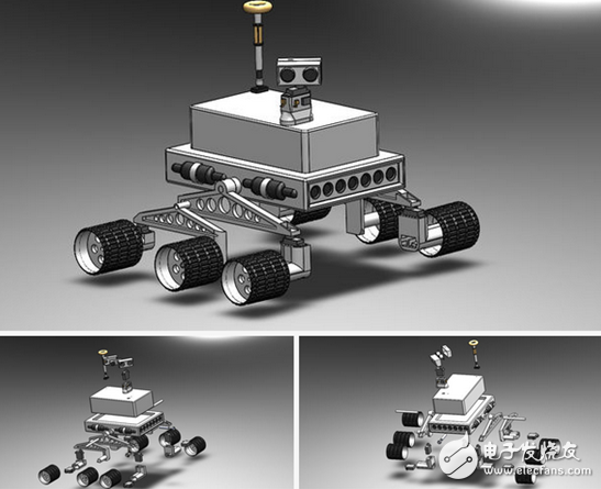
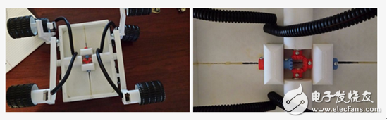
Most of the parts of this model can be printed directly on a 3D printer. Prior to this, the model reconstruction of the STL file has been completed. Four modified continuous rotary servos will need to be mounted on the drive wheel and the drive housing. The center set of the hub can be freely rotated. The black wire loop is used to hide the wires that are lifted from the drive housing and bend the rear drive housing. 5/16" wooden pins are cut into different sizes to connect the main arms to the center differential system. The rubber paint applied to the wheels is designed to increase the traction of the outer surface. To the extent of tolerance, to ensure The system is working properly and maybe some extra tools are needed. The assembly process is very simple and can be stripped from those 3D explosion pictures. To make the overall look good, you can buy some models of paint and a little aluminum foil to hide the wires. .
Step 3: Control System
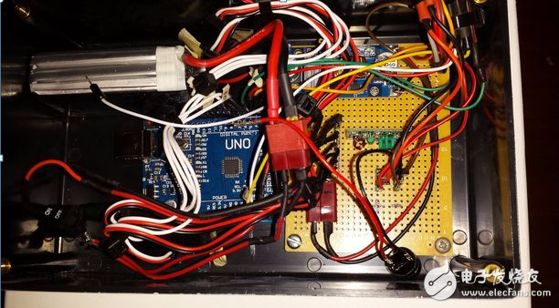
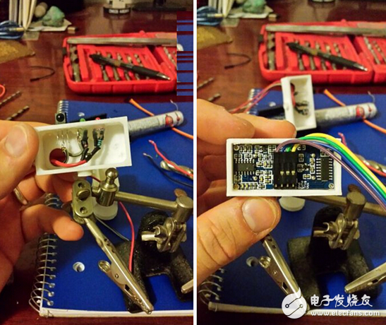
The control system was started with the support of a 1300 mA lithium polymer battery. This battery is an integral part of the overall system, although it was originally purchased for the purpose of buying a spare battery. When the power supply voltage is sent to the adjustable voltage regulator, it is set to about 6.81v and is adjusted to about 5.08v, and can reach about 5V through arduino. However, because the continuous servo system receives a 6.71v voltage source and is not a 5v source, it does not operate normally. However, this problem is solved by adjusting the voltage regulator to 5.08V. Therefore, after passing through the voltage regulator, the voltage is sent to the Arduino and other components. The infrared receiver, LED, and ultrasonic sensor are all mounted on the outside of the servo. In order to facilitate the connection of Rove's components to the power supply and grounding, it is best to solder the two rows of components first. You will need to solder two rows to the PCB board to distribute all power and ground connectors for the various components of the lunar rover.
Step 4: Circuit diagram
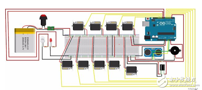
The above picture shows the specific distribution of the components and wires of the schematic of this work. Each component is assigned a reasonable voltage and a signal sent from the Arduino board. To facilitate easy disconnection of system components for replacement or use in other projects, a T-connector can be used. In this figure, it only shows how the components are connected. The pin configuration is inconsistent with the Arduino sketch. In the actual production, please refer to the Arduino sketch for proper pin configuration.
Step 5: Sketch of Arduino
It should be noted that the value set for the stop position of the continuous rotation servo needs to be changed from time to time, because the general resistance used to disperse the voltage on the servo is not accurate, and not every one will get the same value. For example, someone's servo stop position is at 89, 88, 66, 69 degrees. In theory, the stop position should be at 90 degrees, but, as mentioned earlier, the general resistance used for the project is Not very precise. It should also be noted that any infrared remote control can be used for this project. However, it should be noted that the value of the remote control universal button will be different from the value on the Arduino sketch. There are videos on YouTube about how to find the value of your IR remote button.
Step 6: Final product and assembly
When the current button is pressed, the rudder continues to move forward until the stop button is pressed. When the steering button is pressed, the steering gear starts to work, and the wheel will drive the steering gear to turn in the direction of the will. If the steering gear is too close to the target object, the red LED will flash and the buzzer will start. To stop using, simply press the deactivate button and the main unit, and the object in its vicinity will no longer be detected and sensed.
This article is selected from the electronic enthusiast "Security Technology Special", more quality content, download now

The typical Distribution Box is equipped with a solid case that is capable of protecting the interior components from various adverse conditions, such as excessive exposure to heat or cold. The wiring and other parts that are contained in the box are usually mounted within the interior, helping to lessen the potential for the components to be damaged during any type of shifting that would otherwise create some type of abrasive action on wire coverings and other elements.
We have a lot of Distribution Point Box,including 1pair drop wire box,4pair STB Module box,10pair Distribution Point Box,20pair DP box.What's more,we can provide you 10pair pouyet DP box.
The distribution box made of ABS, PC,have good quality and good price.

Distribution Box
Waterproof Distribution Box, Outdoor Distribution Box, Distribution Box
NINGBO YULIANG TELECOM MUNICATIONS EQUIPMENT CO.,LTD. , https://www.yltelecom.com