Customer question 1: The customer uses the S7-1200 PID program block, and the feedback value used is INPUT. After starting auto-tuning, the input value exceeds the setting range error and the auto-tuning function cannot be started.
Answer: After many exchanges with the user, it is found that the problem is the memory address conflict: The customer uses the INPUT input variable, and the upper limit of the calibration after the analog input processing program is 100.0, and the lower limit is 0.0. The allocated storage address is MD516, and the MW516 and MD518 addresses are also used in the client's program content. As a result of address conflicts, the MD516 data is modified so that the data stored in the MD516 memory is greater than 100.0. When auto-tuning is initiated, an error occurs when the input value exceeds the setting range. Extended knowledge 1. MD516 includes 4 bytes: MB516, MB517, MB518, MB519, when using MD516 register, other programs cannot use MB516, MB517, BM518, MB519. Otherwise, address conflicts will occur, and the saved data will be modified or lost. In M area and V area of ​​S7-200; M area of ​​S7-300 / S7-400 needs to pay attention to this problem.
2. The difference between the two feedback data INPUT / INPUT-PER of S7-1200 PID and the relationship with Setpoint. INPUT is the field instrument measurement data, which is converted into actual engineering data after program calibration. The data type is real. INPU-PER is the field instrument data directly tested through the analog channel, without data calibration, the data type is WORD. The data can be directly calibrated through PID configuration and converted into actual engineering quantities. This method is recommended. Setpoint: set value, PID system adjusts the output device to make the feedback value equal to the set value. The setting range is the upper and lower limits of the feedback value calibration. 3. The difference between Output, Output_PER, and Output-PWM, these three signals are all output signals, Output and Output_Per are a group, and Output is a percentage, that is, 0% ~ 100%, which means that the control device is fully closed or fully open. Output_Per is directly output to the analog channel, and the output integer is 0 ~ 27648. Output_Pwm output is a pulse width signal, a digital output, which is different from the above two signals and is used alone. Recommended configuration process: as shown in Figure 1

Figure 1 as Figure 2 Basic parameter configuration feedback and output configuration

Figure 2 Figure 3 Calibration of feedback data
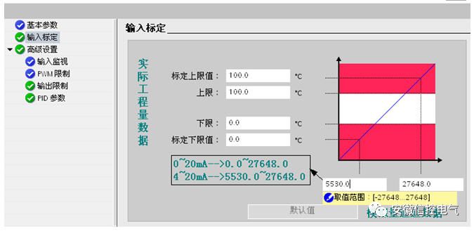
image 3
Customer question 2: How to start the auto-tuning of S7-1200, the set value of the client is too close to the feedback value, and “start auto-tuning†cannot be used
Answer: When all parts of your system have been prepared, you can use auto-tuning. The auto-tuning function is that the system will automatically optimize or calculate PID parameters. It is a method of debugging. During normal operation, it is not necessary to run the auto-tuning debugging program.
The method is as follows: Step 1: Start the test
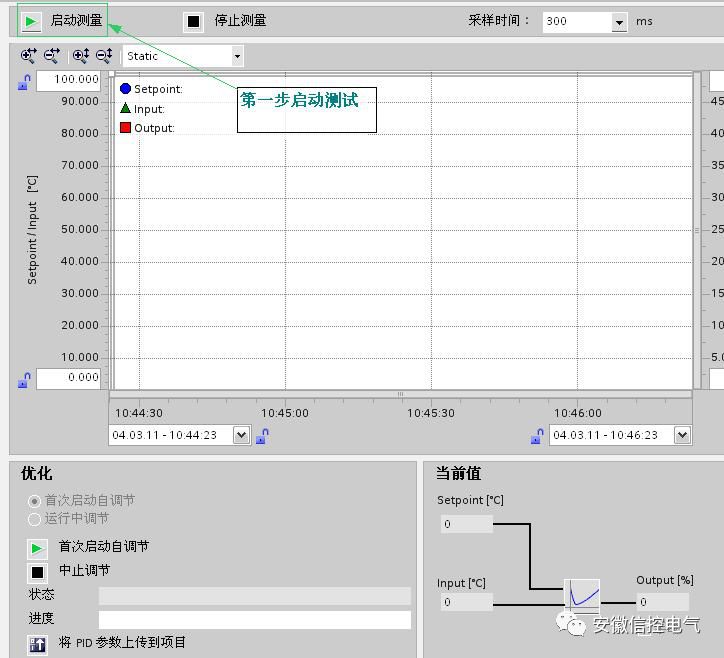
Figure 4 Second step: Set value setting for the first start self-tuning: It is recommended to use the "start first self-tuning" for the first self-tuning, to avoid the system from diverging and not working properly. The set value requirements: set Fixed value-feedback value (calibrated)> 0.3 * upper limit of feedback value-lower limit and set value of feedback value-feedback value (calibrated)> 0.5 * set value running auto-tuning: fine-tuning, PID parameter verification After the first auto-tuning, it is recommended to start running auto-tuning and check the PID parameters again. Setpoint requirements: setpoint – feedback value (calibrated)

Figure 5 Step 4 completion status
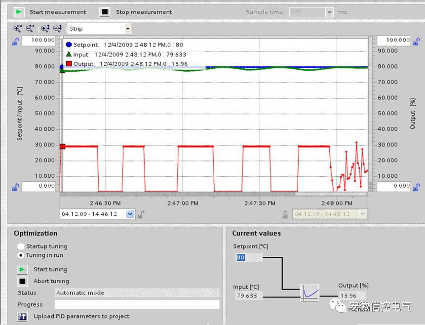
Figure 6 above is the two problems encountered by the user in the actual situation on the spot. However, for the PID, I have done the following problem expansion, I hope to help you further.
Problem: When the S7-1200 PID runs normally, an error occurs and how to recover it.
Answer: In the program block PID_Compact, when the pipe angle Error = 1, it indicates that the current PID running status is in error. To restart the PID function, you need to modify the PID mode-PID_CompactDB.sRet.i_Mode. To resume PID operation, before resetting the PID, you need to confirm that the error has been eliminated. The PID cannot be restarted by other methods, including the Reset function. The specific procedure is shown in Figure 7
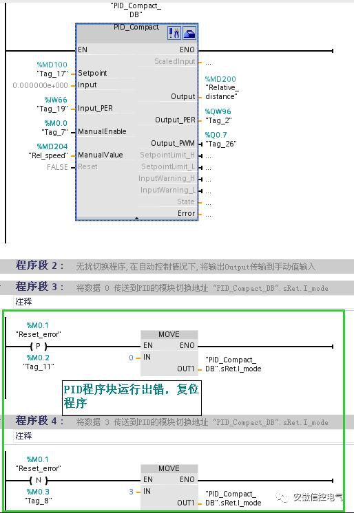
Picture 7
The PID of Siemens is still very strong. It is very stable after self-tuning. I have 5 heating zones that need to work. The other 4 zones can work normally with the PID made by myself, but there is one zone that can not always reach the required temperature deviation of 20 degrees. about
Then the self-tuning with the PID function block of S71200 is very good and the temperature difference is within 0.5 degrees.
The problem is that when the input value of the module exceeds the limit, the PID working block will report a fault reset failure, and it will not work properly after being powered on again.
At this time, you need to make a small program that resets itself and reset the function block.
When there is a fault, the function block is automatically reset, but the state value of the function block will become 0 at this time, and the heating will not work when the state is 0.
To make a small program by yourself, when the value of the status word is zero, assign 3 to the following address "PID_Compact_DB_1" .sRet.i_Mode is OK. After doing this, my heating function PID has no problems. i_Mode
A solar Controller is an electronic device that controls the circulating pump in a solar hot water system to harvest as much heat as possible from the solar panels and protect the system from overheating.
Two kinds solar controller included:
1.PWM Controller
PWM stands for Pulse Width Modulation. PWM charge control devices can be explained as an electrical switch between batteries. The switch can be quickly switch on and switch off. Therefore, desired voltage can be obtained to charge the batteries. The charge current will be slowly decreased as the batteries charged.

Lithium Battery Pwm,Pwm Solar Charge Controller,Home Solar Controller Cost ,20A Pwm Controller
NANTONG RONGCHANG IMPORT&EXPORT CO.,LTD , https://www.ergsolarcn.com