Orthogonal Frequency Division Multiplexing (Orthogonal Frequency Division Multiplexing, OFDM) technology has become a hotspot in the fourth generation of mobile communication research, and OFDM synchronization is also a key technology of OFDM. Carrier interference. The current OFDM synchronization algorithm is based on the data symbol method proposed according to the principle of OFDM. Its advantages are fast capture and high accuracy, suitable for packet data communication. Partial OFDM block. Data symbol-based algorithms can be divided into two categories: methods based on training symbols (pilot codes) and methods based on cyclic prefix (CP), in which PN sequence-based synchronization algorithms are also based on training symbols.
1 Frame, symbol timing and frequency offset estimation synchronization algorithm based on PN sequence
The literature proposes a method of pilot superposition, that is, pilot and OFDM symbols are added, and the correlation of pilot symbols is used to realize timing and frequency offset estimation. Since the PN sequence has good autocorrelation, the PN sequence can be used as a pilot symbol.
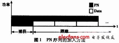
Figure 1 shows how to add a PN sequence. Synchronization is divided into two steps: frame synchronization and symbol synchronization. Several OFDM symbols form a frame, and several identical short symbols (training symbols) are inserted in front of each frame for frame timing and coarse frequency offset estimation. A PN sequence with the same symbol length is superimposed on each OFDM symbol to realize symbol timing and accurate frequency offset estimation. Since the PN sequence is not directly inserted between the information data, the system bandwidth is saved, but in order to improve the synchronization effect, the energy of the PN sequence cannot be too small, otherwise it will be overwhelmed by noise and useful signals, so this pilot superposition method It is at the expense of increased transmit power.
Taking symbol synchronization as an example to analyze the algorithm, ignoring the length of CP, the received signal can be expressed as:
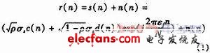
In formula (1), c (n) represents the PN sequence, d (n) is the data sequence, n (n) represents the AWGN, and εf is the normalized frequency offset. If
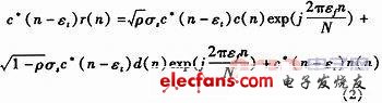
Since the correlation between the PN sequence and AWGN and d (n) is very small, the last two terms in the above formula can be approximated to 0. As can be seen from the first term, when the PN sequence and the PN sequence included in each symbol After finding the correlation, a peak will appear at the boundary of the symbol, which can be used to achieve symbol or frame timing. In order to realize the frequency offset estimation, the correlation value must also be multiplied by the shift, that is:
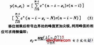
In formula (4), λ [n, 0] represents the estimated value of the starting point of the symbol, and K represents the length of the PN sequence. Generally speaking, the length of the PN sequence is the same as the length of the symbol. A same PN sequence can get a larger frequency offset estimation range, which can be expressed as:
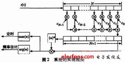
Figure 2 shows the block diagram of the system implementation of the algorithm. The received signal is correlated with the known PN sequence, the length of the PN sequence is assumed to be N, and then the correlated value is stored in a register of length N + 1, the conjugate value is obtained, and the value of the last N bits Multiply.
Under multipath channels, this algorithm can also achieve better frame synchronization. This is because the symbols used for frame synchronization do not include data symbols and will not interfere with the PN sequence; the good auto-correlation of the PN sequence makes the peak used for the start of frame decision very sharp, and the longer the PN sequence, the better the correlation. The greater the peak energy, the stronger the resistance to AWGN.
Hybrid Stepper Motor,Stepper Motor,Standard Hybrid Stepping Motor,Linear Hybrid Stepping Motor
Changzhou Sherry International Trading Co., Ltd. , https://www.sherry-motor.com