Source: Allion Labs
With the rapid development of wireless communication technology and the continuous evolution of specifications in the past decade or so, various wireless technologies, whether GSM, GPS, WLAN (such as Wi-Fi), Bluetooth, etc., have gradually emerged and become popular in daily life in.
The wireless communication technology itself is already profound, and when it is introduced into various electronic devices and application fields, the problems of electromagnetic interference (ElectromagneTIc Interference, or EMI) and electromagnetic compatibility (ElectromagneTIc CompaTIbility, EMC) must be considered To prevent the related functions from being interfered and causing signal degradation, affecting their normal operation. However, despite the fact that laws and regulations have been established in various parts of the world to focus on the restrictions on electromagnetic radiation and RF (Radio Frequency), it is difficult to have a situation where different communication modules may interfere with each other. Set a fixed standard to prevent or solve related problems, which has become the most important focus for product developers to overcome.
In addition, coupled with the recent boom in portable devices and the diversification of communication functions, these related communication modules and antennas must be designed to be lighter, thinner, and smaller in size to meet the needs of mobile applications. This makes it even more difficult to optimize the design of products. To build more different wireless modules and antennas in extremely narrow and streamlined spaces, these components are bound to be more likely to produce noise interference and affect their transmission performance, because it is often observed that the transmission distance becomes shorter , Reduced transmission rate, etc. are not conducive to product communication performance. In this article, Allion Labs, Inc. will introduce how to correctly measure wireless communication signals and conduct electromagnetic compatibility analysis in the context of wireless communication, hoping to communicate with relevant developers and provide technical reference.
Complex communication environment: deterioration of reception sensitivity (De Sense) due to platform noise
First of all, let ’s think about the possible situation of the average consumer when using the current new handheld device (whether it is a smartphone or a tablet): when the meal time comes, consumers want to find a nearby restaurant, they can take out their mobile phones, through Click to open a pre-downloaded application, and then use the voice control method to say the type of cuisine you want to choose. Then, the application will send the received voice message to the application provider's server on the network for interpretation. Locate and search the user's location, and display the qualified options and even the map on the screen, and the user can find the appropriate ideal restaurant according to the map.
In fact, in this seemingly simple operation process in just a few seconds, the operation of many components is included behind, including the sensing of touch screen, the combination of products (hardware) and user operation interface (software) , The microphone transmits the clean user voice by eliminating background noise, the activation of the 3G module, the ability to connect with the neighboring base station, the role of the GPS positioning system, the return of the search results of the server, etc. Although for the user, what they feel is "good or bad", but for the developer, it must be verified in detail from the mechanical structure, component selection, software and hardware integration to the communication module behind it. Create good use experience and fully achieve the purpose of the product.
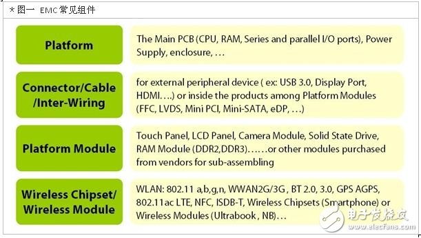
Therefore, to understand all the components that may generate electromagnetic signals in the entire communication environment of the product can be said to be an important prerequisite for the construction design. From Figure 1, we can clearly see that in the current general new devices, there are four main types of components that generate electromagnetic signals. If the signals emitted by these components cause mutual interference due to poor design, they can be called carriers. Noise (Platform Noise). These four types of components include system platforms (such as central processor, memory, power supply), internal and external connector coupling paths (such as various transmission interfaces such as USB, HDMI), and outsourced platform modules (such as touch Screens, camera lens modules, solid-state drives and other components assembled after outsourcing from manufacturers) and wireless chipsets / wireless modules (such as Wi-Fi 802.11 a / b / g / n, Bluetooth, GPS), etc. All kinds of components need to be meticulously measured and calculated to accurately find the best circuit design and properly build the overall product to avoid interference with each other and minimize the risk of all possible problems.
What is the so-called Platform Noise Interference? For example, the panel is currently the largest component of all control devices, and any signal emitted by the antenna in the device will hit the panel, and the noise emitted by the panel will also enter the antenna; similarly, the radio waves emitted by the antenna will also Affects each interface; and the signals sent by different modules will also become each other's noise, which is called the stage noise interference. When these modules and components are operating at the same time and the interference cannot be controlled below a certain limit, the phenomenon of "Degradation of Sensitivity (De Sense)" will occur, affecting the normal operation of the device's wireless performance. .
For example, in the same frequency band, when mobile phone A can receive signals of 1000 channels, and mobile phone B can only receive 500 channels, in actual experience, users will think that mobile phone B has poor receiving capabilities. Since antennas, filters, and front-end circuits do not perform particularly poorly on any particular channel, in summary, this may be because the design of the B mobile phone is not exhausted, and it is interfered by the noise of the carrier, resulting in The so-called reception sensitivity deteriorates.
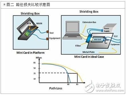
The method of measuring the noise interference of the stage is not difficult. You can choose a clean environment without external interference (such as an electromagnetic wave isolation box), and measure the signal throughput (Throughput) result of a single wireless module connected to the circuit board through a separate measurement ( (The yellow line in Figure 2), and the signal throughput result of measuring the function of the module built in the product system platform (as shown in the blue line in Figure 2), and comparing the two, you will find that it acts on the product Signal degradation is apparent in the platform. The difference between the path loss (Path Loss) between the two can be regarded as the interference caused by the platform noise.
It must be emphasized here that the existence of stage noise is inevitable. We cannot reduce the noise to zero, because the module must be powered by the system, and the location of the module will also affect other neighboring modules. With the interface, there is bound to be noise. However, although the existence of carrier noise is inevitable, you can try to minimize its interference without affecting the communication performance. This is why we have to measure the noise and find the source of the interference.
However, it is not difficult to measure the noise interference of the stage, but to verify the sources of the stage noise and the degree of interference caused by individual sources, a very complicated and meticulous measurement method is required, which is definitely a developer A big challenge. Just controlling the variables and cross-measuring the components that may cause interference can produce thousands of combinations, such as between different communication channels, Bluetooth and Wi-Fi, Wi-Fi and 3G, 3G and GPS Waiting for it, it may cause signal loss due to signal coexistence (Co-existence), crosstalk (Crosstalk) and other conditions. How to use the correct measurement sequence and techniques and automate the time-consuming cross-measurement between them to effectively determine the main noise source is the study.
The primary focus of noise reduction: make a reasonable noise budget (Noise Budget) for modulation
After understanding that the interference of the platform noise will cause the deterioration of the reception sensitivity, and how to measure it, the next important point is to set the allowable value of the device noise, that is, to formulate a reasonable noise budget (Noise Budget) In order to make the most suitable adjustment for the device. In other words, after learning how the wireless communication technology can be demodulated (for example, it is known that the deterioration of the 3G module can be demodulated through the GPS module), the noise level and Eb / No (system average signal-to-noise ratio) ), The proper noise tolerance can be set to correct (not eliminate) noise interference.
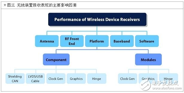
However, such correction is not a single component correction, but requires a series of interlocking verification and modification. For example, when the screen of the device interferes with the antenna reception, not only the panel itself, but also the display card, input and output power, circuit design, LVDS interface, etc., even the surface of the antenna All current distribution methods require modulation. As can be seen from the simplified diagram in Figure 3, there are many variable factors that affect the signal reception capability of wireless devices, and all of them are dependent on each other. Therefore, it is the key to effectively improve the quality of the product to set a reasonable noise budget based on the actual noise situation of the stage and adjust it accordingly to reduce the noise.
Qunsuo aims at providing our customers high qualified Industrial Rugged Pda. In order to meet customers using environment, our PDAs all pass IP65 certification. With the stable quality of our Handheld Android Pda, we gain many reliable customers, help many customers provide IT solutions. If you are also looking for reliable PDA manufacturer partner, Qunsuo will be your good choice. Welcome to contact us for more details!

Industrial Rugged Pda
Android Pda Europe,Pda With Desktop Charger,Rugged Handheld Pda Honeywell,Handheld Barcode Scanner Pda
Shenzhen Qunsuo Technology Co., Ltd , https://www.qsprinter.com