![]()
Car Audio Crystal 3.2*2.5mm 3225 24M (24.000MHZ) 20PF 10PPM 20PPM 30PPM
![]()
Probe domestic switch needle KG-300K needle head diameter is 3.0mm normally open switch needle
![]()
Photocoupler
The 555 circuit, which contains two voltage comparators, a basic RS flip-flop, and a discharge switch T, the comparator's reference voltage is provided by a voltage divider consisting of three 5K resistors. They respectively make the non-inverting input of the high-level comparator A1 and the inverting of the low-level comparator A2, and the reference levels of the input terminals are 2/3VCC and 1/3VCC. The outputs of the A2 and A2 control the RS flip-flop state and Discharge tube switch status. When the input signal is from the 6 pin, that is, the high level triggers the input and exceeds the reference level 2/3VCC, the flip-flop resets, the output of the 555 pin 3 outputs a low level, and the discharge switch tube is turned on; when the input signal is from 2 The input of the pin is lower than 1/3VCC, the trigger is reset, the 3 pin of 555 outputs high level, and the discharge switch tube is cut off. RD is the reset terminal (4 pins). When RD=0, 555 outputs a low level. Usually the RD end is open or connected to VCC.
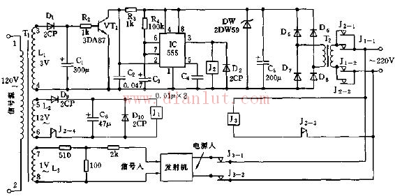
Sounder sound remote control switch circuit diagram