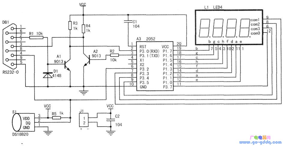
First, the system principle block diagram and circuit schematic
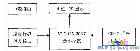
System block diagram (shown above), each component function:
1. The minimum system of the single-chip microcomputer, the minimum system of the single-chip microcomputer consisting of STC12C2052 and reset capacitor C1, as the main controller of the system.
With internal RC oscillation (5.6MHz), no external crystal is required. For a detailed introduction to the STC microcontroller and refer to the relevant website.
2. Temperature sensing and interface, DS18820 is a one-wire bus interface, hardware connection is relatively simple, after +5v power supply, the data terminal (DQ) can be directly connected to the microcontroller I/O through R5 (1K) pull-up resistor, and connected To the DB9 serial port connector, if the remote temperature is measured, the external DS18820 can be connected through the serial port head without using an additional power supply (true two-wire connection).
3.LED digital tube, consisting of 4 digits and 8 segments of digital tube, the segment control terminal is connected to the P1 port of the single-chip microcomputer set to strong pull-up, and the position control terminal is connected to the P3.3-P3.7 port (P3.6CPU is not exported) Used to display the current temperature. The display method is “××.××â€, and two decimal places are taken.
4. Program download interface, since the computer serial port level is ±15V for 0 and 1, it is necessary to perform level conversion when connected with this circuit. In the following figure, Al, A2, Rl, R2, R3, R4, Dl are composed. A simple RS232-TTL conversion circuit, Al inverts the serial port signal of the computer into a 5V signal and sends it to the serial port receiving terminal RXD. The TXD signal of the single chip is inverted by A2 and sent to the DB9 standard serial port. It is connected to the COM port of the computer to complete the debugging and downloading of the program.
5. Power interface, the external +5V DC power supply is connected by Jl.
Second, the circuit production
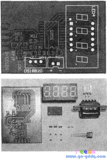
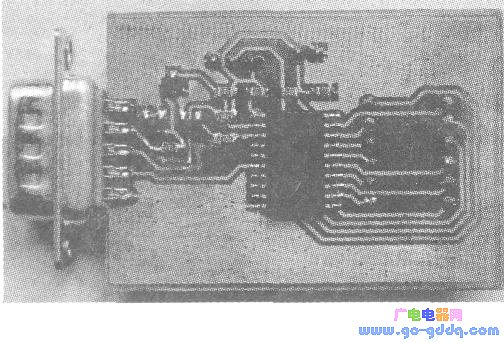
The board is designed with Prote199 software. Considering the principle of convenient processing and cost saving, this work is designed as a single panel. Most of the components used are patch components, occupying a small circuit board area, and using 15 MIL width wires can prevent heat transfer. The occurrence of printed breaks, easy to make the board, the printed board and the physical photos of the components are shown above (the left side is the copy in Prote199. Since the PCB is set to the bottom in Ptotel99, the two figures are There is a visual relationship between the eyes).
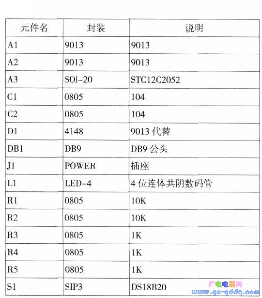
The circuit board diagram is printed on the transfer paper by a laser printer, and can be transferred onto the copper plate by high-temperature rolling. The so-called immersion of ferric chloride can make a truly usable circuit board. After that, the hardware circuit can be soldered. In this work, the list of components is shown in the table below. The figure below shows the physical picture after soldering.
Third, software design
In this example we used C language and selected KeiluVision2 as the development environment. The programming in this example includes the following parts: program initialization section, timing interrupt LED display section, read 18820 data section, and data calculation section, where the difficulty lies in timing interrupting the LED display portion and the driving portion of the DS18820.
The software flow is shown below:
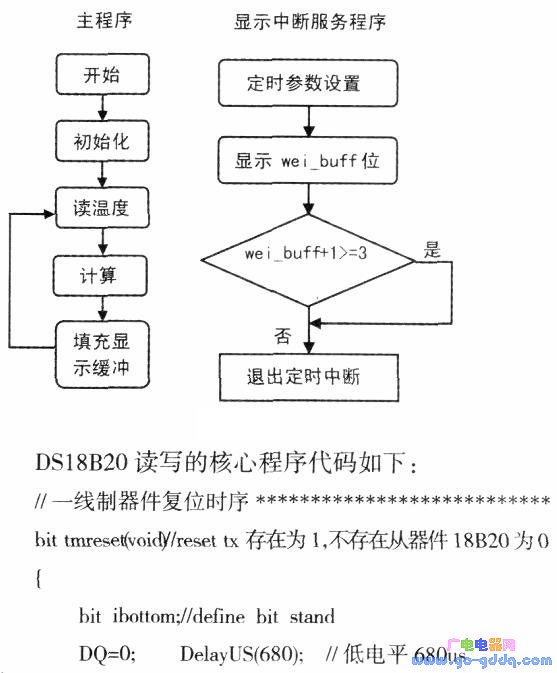
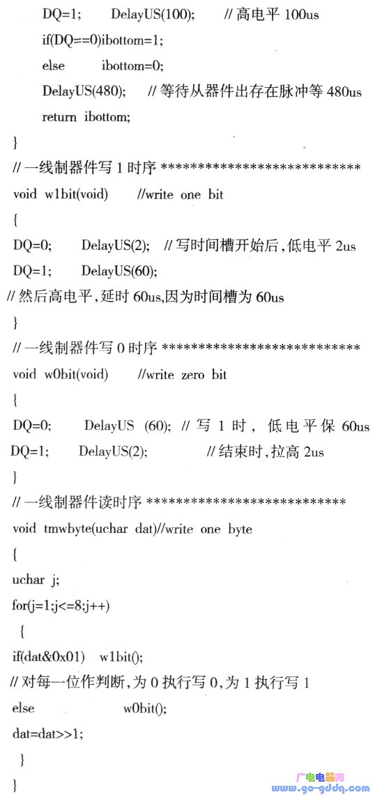
In these routines, the delay time is more demanding, which is also the working benchmark for the 1-wire device.
Fourth, software and hardware debugging
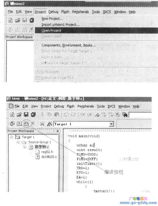
We provide the entire engineering program in the Keil uVision2 development environment, including complete C code (with comments) and related supporting documentation. Open the Keil uVision2 development environment, open the "temp.Uv2" project provided in this article, and enter the programming interface.
After each change of the program, click the button shown below to compile. If there is no error in the status bar, you can find a target file of temp.hex in the project directory, we can use the programming software provided by STC microcontroller. Download to the design to see the running effect.
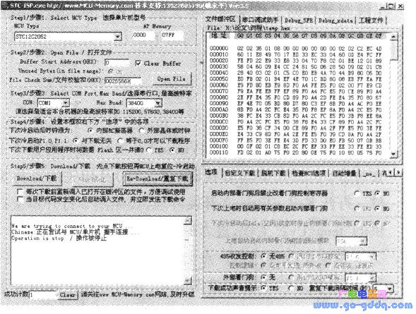
After generating the target code, we can download it through STC-ISP software, search and install STC-ISP on the network, and need to set the CPU type and communication port (usually coml) when using this software for the first time. Since the simple level conversion circuit is used, the baud rate can be set lower. The cross-connected dual-head serial cable connects the system to the COM port of the computer. After opening the target document with "openfile", you can use the Dowdload button to program. Operation (add power to the target board after clicking this button), as shown below.
Five, notes and troubleshooting
In the design, we should pay attention to the following problems and difficulties:
1. In terms of LED segment control connection, in order to facilitate circuit board wiring, there is no commonly used sequential connection method, but only the segment control code is affected during use.
2. In the simple level shifting circuit, in order to facilitate the purchase of the device, 9013 is used instead of the anti-reverse breakdown diode in the figure.
3. When purchasing components, LED-selected common cathode digital tube, and the power supply voltage must be between 5 and 5.5V (5V power supply for computer USB communication port can be used).
4. During the welding process, the temperature should not be too high. If the welding time of one of the pins is longer than 20s, in order to prevent the pad from falling off, please take a break and continue.
5. If it is inconvenient to purchase the transfer paper, you can use the layer to replace it in time. If there is no transfer machine, you can use an electric iron (the temperature is controlled at about 120 °C). If the effect is not good, you can do it twice.
6. When soldering the chip components, first tin-plating on one of the pins, then mounting the component, soldering the end, and finally soldering the other end, which is beneficial to improve the success rate.
7. In the C language, if the precise delay is not easy to do, you can experiment with a program to determine the length of the delay.
8. When reading the 18820, due to the strict timing requirements of such components, if the timing interrupt arrives at this time, it will affect the normal operation of the 18820. Therefore, when reading the 18820, it is necessary to temporarily turn off the interrupt until the temperature data is obtained. Interrupt, continue to display, but due to the high speed of the microcontroller operation, there is no impact on the naked eye.
Possible failures and solutions, methods:
1. Pay attention to the serial number of the computer. If you are not sure, please go to the "System" - "Hardware" - "Device Management View" in the control panel. If you use a notebook without a serial port, you can purchase a usb to convert to a serial port. Connected to use.
2. If you confirm that the serial port connection is normal, the problem of multiple programming connections is not available, indicating that the purchased 9013 three-stage tube is not enough amplification. Please connect a lOk resistor directly to the Txd and the power supply.
Other capacitors
Ac Filter Capacitor,Power Saver Capacitor,Line Filter Capacitor,Low Voltage Capacitor
YANGZHOU POSITIONING TECH CO., LTD. , https://www.cnpositioning.com