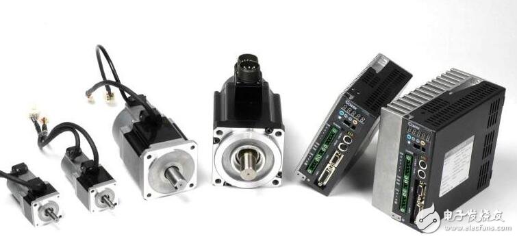
The servo motor is also called the execution motor, or the control motor. In an automatic control system, a servo motor is an actuator that converts a signal (control voltage or phase) into a mechanical displacement, that is, changes the received electrical signal to a certain rotational speed or angular displacement of the motor. Its capacity is generally 0.1-100W, and commonly used is below 30W. Servo motors are divided into DC and AC.
1. Electric brake method:
(1) Dynamic brake (also known as energy brake) consists of dynamic braking resistor, which shortens the mechanical feed distance of the servo motor through energy consumption braking during fault, emergency stop and power failure.
(2) Regenerative braking (also known as feedback braking) means that the servo motor returns the energy generated by the braking to the DC bus through the inverter loop when it is decelerating or stopping, and is absorbed by the RC circuit.
2, mechanical brake method
Electromagnetic braking is the shaft that locks the motor by mechanical means. Users often confuse the effects of electromagnetic braking, regenerative braking, dynamic braking, and choose the wrong accessories.
The dynamic brake consists of a dynamic braking resistor that shortens the mechanical feed distance of the servo motor by energy braking during faults, emergency stops, and power outages.
The dynamic brake is composed of a dynamic braking resistor, which shortens the mechanical feed of the servo motor by energy braking during fault, emergency stop, and power failure.
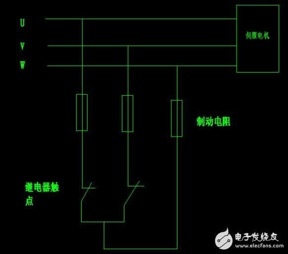
Generally, three braking wires are connected to the three wires of the servo motor's UVW phase. These three resistors are connected to a relay. When the servo motor works normally, the three phases of the relay are not short. When the servo motor is to be braked, the relay will be powered off and the three phase lines will be connected together and the brake will start.
Regenerative braking means that the servo motor returns the energy generated by the braking to the DC bus through the inverter loop when decelerating or stopping. Absorbed by the RC circuit.
Electromagnetic braking is the shaft that locks the motor by mechanical means.
The difference between the three:
(1) Regenerative braking must be performed when the servo is working normally. The motor cannot be braked during faults, emergency stops, power failures, etc. Dynamic brakes and electromagnetic brakes do not require power when working.
(2) The work of regenerative braking is automatically performed by the system, while the operation of dynamic brakes and electromagnetic brakes requires external relay control.
(3) The electromagnetic brake is normally started after SV OFF, otherwise the amplifier may be overloaded. The dynamic brake is normally started after SV OFF or the main circuit is de-energized, otherwise the dynamic braking resistor may overheat.
Note on selecting accessories:
(1) Some systems such as conveyors, lifting devices, etc. require the servo motor to stop as soon as possible. In the event of a fault, an emergency stop, or a power failure, the servo does not regeneratively brake and cannot decelerate the motor. At the same time, the mechanical inertia of the system is large. At this time, the dynamic brake should be selected according to the weight of the load and the working speed of the motor.
(2) Some systems need to maintain a large output torque and a long stop time to maintain the static position of the mechanical device. If the self-locking function of the servo is used, the motor will overheat or the amplifier will be overloaded. In this case, choose a motor with an electromagnetic brake.
(3) Mitsubishi's servo has a built-in regenerative braking unit, but when the regenerative braking is frequent, the DC bus voltage may be too high. In this case, a regenerative braking resistor is required. Whether the regenerative braking resistor needs to be equipped separately, and how much regenerative braking resistor is used can refer to the instructions for use of the sample. It should be noted that the number of brakes on the sample list is the data of the motor at no load. In the actual selection, the inertia ratio should be calculated according to the load inertia of the system and the motor inertia on the sample. Then divide the number of brakes on the sample list by (inertia ratio +1). The data thus obtained is the number of brakes allowed.
Servo motor control methodThe servo motor is a device that assists motor acceleration. The servo electromechanical control speed and position are very accurate. Servo electromechanical is a motor controlled by a closed-loop controller. It is a feedback from multiple encoders of an ordinary motor. It can calculate the output target value according to the given and feedback, and control the movement speed and displacement of the motor. Usually the servo electromechanical control methods are:
The servo motor is generally controlled by three loops. The so-called three loops are three closed loop negative feedback PID adjustment systems. The innermost PID loop is the current loop. This loop is completely carried out inside the servo driver. The Hall device detects the output current of each phase of the driver to the motor, and the negative feedback gives the current setting PID adjustment, so that the output current is as close as possible. Equal to the set current, the current loop is to control the motor torque, so in the torque mode the drive has the smallest operation and the fastest dynamic response.
The second ring is the speed loop. The negative feedback PID is adjusted by the detected signal of the motor encoder. The PID output in the ring is directly set by the current loop, so the speed loop control includes the speed loop and the current loop. In other words, the current loop must be used in any mode. The current loop is the fundamental of control. At the same time of speed and position control, the system actually performs current (torque) control to achieve corresponding control of speed and position.
The third ring is the position loop, which is the outermost ring. It can be built between the drive and the motor encoder. It can also be built between the external controller and the motor encoder or the final load, depending on the actual situation. Since the internal output of the position control loop is the setting of the speed loop, the system performs all three loop operations in the position control mode. At this time, the system has the largest amount of calculation and the slowest dynamic response speed.
1. Torque control: The torque control mode is to set the external output torque of the motor shaft through the external analog input or the assignment of the direct address. The specific performance is, for example, 10V corresponds to 5Nm, when the external analog quantity is set. When the motor is rated at 5V, the motor shaft output is 2.5Nm: if the motor shaft load is lower than 2.5Nm, the motor rotates forward, the motor does not rotate when the external load is equal to 2.5Nm, and the motor reverses when it is greater than 2.5Nm (usually generated under gravity load) ). The set torque can be changed by changing the analog setting in real time, or by changing the value of the corresponding address by communication. The application is mainly used in the winding and unwinding devices which have strict requirements on the material stress, such as the wire drawing device or the fiber drawing device. The torque setting is changed according to the change of the winding radius to ensure the stress of the material is not It will change as the winding radius changes.
2. Speed ​​mode: The rotation speed can be controlled by the analog input or the frequency of the pulse. The speed mode can also be positioned when the outer ring PID of the upper control device is controlled, but the position signal or direct load of the motor must be used. The position signal is given to the upper feedback for calculation. The position mode also supports the direct load outer loop detection position signal. At this time, the encoder at the motor shaft end only detects the motor speed, and the position signal is provided by the direct final load end detection device. This has the advantage of reducing the intermediate transmission process. The error increases the positioning accuracy of the entire system.
3. Position control: The position control mode generally determines the rotation speed by the frequency of the externally input pulse. The number of pulses is used to determine the angle of rotation. Some servos can directly assign speed and displacement through communication. Since the position mode has strict control over speed and position, it is generally applied to positioning devices.
The motion servo is generally a three-loop control system, which is a current loop speed loop position loop from the inside to the outside.
1. First, the current loop: the input of the current loop is the output after the speed loop PID is adjusted. We call it “current loop referenceâ€, then the current loop is given and the “current loop feedback†value is compared. The difference is the PID adjustment output to the motor in the current loop. The "current loop output" is the phase current of each phase of the motor. The "current loop feedback" is not the encoder feedback but is installed in the driver inside each phase. The Hall element (magnetic field induction becomes a current voltage signal) is fed back to the current loop.
2. Speed ​​loop: The input of the speed loop is the output of the position loop PID adjustment and the feedforward value of the position setting. We call it “speed settingâ€, and this “speed setting†and “speed loop feedback†value are compared. After the difference is made in the speed loop for PID adjustment (mainly proportional gain and integral processing), the output is the "given loop given" mentioned above. The feedback of the speed loop is derived from the feedback value of the encoder via the "speed operator".
3. Position loop: The input of the position loop is an external pulse (normally, the servo exception is directly written to the address of the drive), and the external pulse is subjected to smoothing processing and electronic gear calculation as the "position loop setting". The calculated value of the pulse signal from the encoder feedback and the deviation counter is calculated after the PID adjustment (proportional gain adjustment, no integral derivative) of the position loop and the value of the feedforward signal given by the position. The given speed loop is given above. The feedback of the position loop also comes from the encoder.
The encoder is mounted on the tail of the servo motor. It has no connection with the current loop. It samples the rotation of the motor instead of the motor current, and has no connection with the input, output and feedback of the current loop. The current loop is formed inside the driver. Even if there is no motor, a feedback loop can be formed by installing an analog load (such as a bulb) current loop on each phase.
Talk about the impact of PID on the difference adjustment system:
1. Separate P (proportion) is a proportional operation of the difference. Its remarkable feature is that there is a difference adjustment. The difference is that after the adjustment process is finished, the adjusted quantity cannot be exactly equal to the set value. There must be a residual between them, and the specific value of the residual can be calculated by the proportional relationship. . . Increasing the ratio will effectively reduce the residual and increase the system response, but it will easily lead to system turbulence or even instability.
2. The separate I (integral) is to make the change speed of the output signal of the regulator proportional to the difference signal. It is not difficult to understand that if the difference is large, the rate of change of the integral link is large, and the ratio of the proportional constant of this link is large. The reciprocal we usually call it the integral time constant in the servo system. The smaller the integral time constant means the faster the system changes, so if the integral speed is increased (that is, the integral time constant is reduced), the control system will be reduced. The degree of stability until the end of the divergence of the shock process, the biggest advantage of this link is that the final adjustment is no residual.
3. PI (proportional integral) is the advantage of combining P and I. The P adjustment is used to quickly cancel the influence of interference, and the I adjustment is used to eliminate the residual.
4. The individual D (differential) is adjusted according to the direction and size of the difference. The output of the regulator is proportional to the derivative of the time. The differential link can only play an auxiliary adjustment role. It can be adjusted with other adjustments. Combined into PD and PID adjustment. . . Its advantage is that it can be adjusted according to the speed of change of the adjusted amount (difference), instead of waiting for a large deviation to start the action, in fact, it gives the regulator some degree of predictability, Increase the system's response to small changes.
The PID constant of the servo current loop is generally set inside the driver, and the user does not need to change it.
The speed loop mainly performs PI (proportional and integral), and the ratio is the gain, so we need to adjust the speed gain and the speed integral time constant to achieve the desired effect.
The position loop mainly performs P (proportional) adjustment. . . For this we just need to set the proportional gain of the position loop.
There is no fixed value for the parameter adjustment of the position loop and speed loop. It depends on the mechanical transmission connection mode of the external load, the movement mode of the load, the load inertia, the speed and acceleration requirements, and the rotor inertia and output inertia of the motor itself. It is decided that the simple method of adjustment is to adjust the gain parameter from small to large in the range of general experience according to the external load, and the integral time constant is from large to small, so that the steady state value without vibration overshoot is the optimum value. Make settings.
When the position mode needs to adjust the position loop, it is best to adjust the speed loop first (the proportional gain of the position loop is set at the minimum value of the empirical value). After the speed loop is stabilized, the position loop gain is adjusted, and the appropriate amount is gradually increased. The response of the position loop is preferably slower than the speed loop, otherwise the speed shock is prone to occur.
The general servo has three control modes: speed control mode, torque control mode, and position control mode.
1. Torque control: The torque control mode is to set the external output torque of the motor shaft through the external analog input or the assignment of the direct address. The specific performance is, for example, 10V corresponds to 5Nm, when the external analog quantity is set. When the motor is rated at 5V, the motor shaft output is 2.5Nm: if the motor shaft load is lower than 2.5Nm, the motor rotates forward, the motor does not rotate when the external load is equal to 2.5Nm, and the motor reverses when it is greater than 2.5Nm (usually generated under gravity load) ). The set torque can be changed by changing the analog setting in real time, or by changing the value of the corresponding address by communication. The application is mainly used in the winding and unwinding devices which have strict requirements on the material stress, such as the wire drawing device or the fiber drawing device. The torque setting is changed according to the change of the winding radius to ensure the stress of the material is not It will change as the winding radius changes.
2. Position control: The position control mode generally determines the rotation speed by the frequency of the externally input pulse. The number of pulses is used to determine the angle of rotation. Some servos can directly assign speed and displacement through communication. Since the position mode has strict control over speed and position, it is generally applied to positioning devices.
3. Speed ​​mode: The rotation speed can be controlled by the analog input or the frequency of the pulse. The speed mode can also be positioned when the outer ring PID of the upper control device is controlled, but the position signal or direct load of the motor must be used. The position signal is given to the upper feedback for calculation. The position mode also supports the direct load outer loop detection position signal. At this time, the encoder at the motor shaft end only detects the motor speed, and the position signal is provided by the direct final load end detection device. This has the advantage of reducing the intermediate transmission process. The error increases the positioning accuracy of the entire system.
4, talk about the 3 ring, servo motor is generally three ring control, the so-called three ring is three closed-loop negative feedback PID adjustment system. The innermost PID loop is the current loop. This loop is completely carried out inside the servo driver. The Hall device detects the output current of each phase of the driver to the motor, and the negative feedback gives the current setting PID adjustment, so that the output current is as close as possible. Equal to the set current, the current loop is to control the motor torque, so in the torque mode the drive has the smallest operation and the fastest dynamic response.
The second ring is the speed loop. The negative feedback PID is adjusted by the detected signal of the motor encoder. The PID output in the ring is directly set by the current loop, so the speed loop control includes the speed loop and the current loop. In other words, the current loop must be used in any mode. The current loop is the fundamental of control. At the same time of speed and position control, the system actually performs current (torque) control to achieve corresponding control of speed and position.
The third ring is the position loop, which is the outermost ring. It can be built between the drive and the motor encoder. It can also be built between the external controller and the motor encoder or the final load, depending on the actual situation. Since the internal output of the position control loop is the setting of the speed loop, the system performs all three loop operations in the position control mode. At this time, the system has the largest amount of calculation and the slowest dynamic response speed.
Splitter: To divide the input signal equally among the different sets; At the same time, these televisions are isolated from each other. Usually there are :2 distribution (divided in two), 3 distribution, etc. Cable TV also has a distributor, which is different from a distributor. The branching device transfers some of the energy to the next stage. Branch devices are often used in cable television networks
DAB Spliter ,DAB Spliter SMA ,DAB Spliter for Car ,DAB Spliter Signal Amplifier ,AM /FM DAB Antenna
Yetnorson Antenna Co., Ltd. , https://www.yetnorson.com