1. Introduction
Inverters often face unexpected voltage transients and surges during operation, which can damage internal electronic components. These damages are typically caused by semiconductor devices such as diodes, transistors, thyristors, and integrated circuits being burned or broken down. According to statistical data, 75% of faults in the inverter control section are due to voltage transients and surges. Such events are common—power grids, lightning strikes, blasting activities, and even walking on carpets can generate static voltages reaching tens of thousands of volts. These are hidden threats that can harm the control and communication ports of inverters. Therefore, to enhance the reliability of inverters, it is essential to implement protective measures against voltage transients and surges.
2. Lightning Protection Ports
Based on engineering practices in frequency converter applications, inverters can be broadly categorized into direct lightning strikes, induced lightning, and conductive lightning. Regardless of the form, these surges typically enter through four main points, known as lightning protection ports. This section illustrates these key areas using a frequency converter as an example.
2.1 Shell Ports
Any inverter or system, whether large or small, can be exposed to direct lightning strikes. For instance, outdoor sensors connected to an inverter may experience lightning discharge, while indoor inverter cabinets could be affected by space discharges when building lightning protection systems discharge. Standards indicate that if the equipment casing experiences a 4kV lightning discharge, it may disrupt the normal operation of the inverter or the entire system.
2.2 Signal Line Port
In the inverter control system, signal transmission requires external connections. These signal interfaces may be impacted by lightning surges. Since external signals often travel through long cables, the standard specifies a line-to-line surge voltage of 0.5kV and a line-to-ground surge voltage of 1kV for a 10/700μs waveform. The signal ports between inverters in buildings are subjected to surge impacts similar to those on power lines, with a 1.2/50 (8/20) μs combined wave. If the limit is exceeded, the signal port and the device behind it could be damaged.
2.3 Power Port
The power port is the most vulnerable to lightning surges, both inductive and conductive. The inverter's power port includes the connection from the power distribution panel to the inverter input and from the inverter output to the motor. Standards specify a line-to-line surge voltage of 0.5kV and a line-to-ground surge voltage of 1kV for a 1.2/50 (8/20) μs waveform. However, this applies to a working voltage of 220V AC. If the working voltage is lower, the standards may not be directly applicable. Even small surges on the power line can affect the equipment’s lifespan over time.
2.4 Grounding Port
Although not specifically addressed in the standard, the grounding port is crucial for inverter protection. During lightning strikes, the grounding port may suffer from ground potential rise or counterattack. Poor grounding can lead to high resistance, causing the equipment to malfunction due to reference potential issues. The grounding port must meet specific requirements for grounding resistance, material, method, and grid design, as well as relate to the equipment’s electrical characteristics and environment. It can also cause damage to DC-powered units through the grounding terminal.
In summary, inverter lightning protection should focus on the four critical ports, as illustrated in Figure 1.
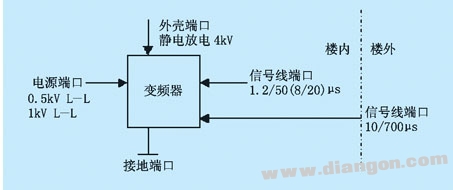
Figure 1: Four Key Ports of the Inverter
3. Inverter Port Protection
3.1 Enclosure Port Protection
The enclosure port is not only about the building structure but also includes the inverter cabinet and its housing. IEC 1312-1 outlines general principles for protecting against lightning electromagnetic pulses. Three main methods include grounding, shielding, and equipotential bonding.
(1) Grounding
IEC 1024-1 describes building grounding for lightning protection, using underground mesh systems. When protecting inverters, power lines and signal cables between buildings should connect to the building grounding system without forming loops. This helps reduce current in the cables by providing multiple parallel paths. Inverter system grounding should avoid direct connection to lightning protection grounds to prevent stray currents from causing interference. A safer approach is to connect two grounding nets via a low-voltage arrester during lightning strikes.
(2) Shielding
Shielding is effective in protecting the inverter casing from lightning. However, economic considerations require selecting appropriate shielding methods based on immunity levels and effectiveness. Shielded cables are widely used in inverter systems. Equipment shielding may be limited by availability, and IEC suggests connecting building reinforcement to metal frames.
(3) Equipotential Bonding
Equipotential bonding reduces potential differences between inverters and metal parts. At lightning protection zone interfaces, it should consider the inverter system within the building. Metal plates and reinforcing bars should be connected to shields. For exposed conductive materials, an equipotential network should be established. While not directly grounded, all such networks have significant ground connections.
3.2 Signal Line Port Protection
There are various mature protection devices, such as inverter signal port protectors and communication port protectors. Factors like transmission rate, insertion loss, standing wave ratio, operating voltage, and current should be considered. If multi-level protection is used, coordination between stages is important.
Transient currents in the signal port can damage internal components like the main board, parallel ports, and signal interface cards. Surges may enter through different channels, especially in Ethernet-based systems. Four possible threats include direct contact with power circuits, static effects on LAN cables, high-energy transients coupled through nearby cables, and differences in ground voltages between network components.
For example, in RS-232 serial and parallel ports, the ground line shares a path with the signal return, making it vulnerable to transient voltages. Signal lines can also transmit surges from outdoor power lines, leading to lightning and static leakage. Advanced systems use transient overvoltage semiconductor discharge tubes, with impact residual voltage being a key parameter. Multi-level protection designs are recommended where possible.
3.3 Power Port
Multi-stage SPDs are generally used for power protection. However, due to the sensitivity of inverter systems, a low-residual voltage protector is necessary, with a residual voltage below the device's withstand capability. Electromagnetic interference must also be considered, so a filtered shunt design is ideal. Two key points to note are: use high-current protectors in the first two stages and a low-residual voltage protector at the end of the inverter. A filter circuit is preferable in the final stage.
When installing SPDs on the power port, attention should be paid to energy coordination, time coordination, and distance coordination. Leads should be as thick and short as possible, and wires should be bundled whenever possible.
4. Conclusion
In variable frequency speed control systems, focusing on inverter port protection has become a critical issue in design and application. As technology evolves, inverter port protection will continue to develop and improve. Ensuring robust protection remains essential for reliable system performance.
Dual Function Key Switches
Dual Function interlock Key Switches is a Key Switches that combines Electric Key Switch and Mechanical Key Lock, which is Simultaneously have power control and could mechanically protect the equipment from invading.
Our company's Key Lock Electrical Switches has mounting dimensions of 12mm and 19mm. This 2 Position Key Switch is widely used in the field of security products, which not only can achieve the function of switching power supply but also could protect customer`s confidential data.Application including buses, cars, motorcycles, ATM and so on.

Below are the specifications:
Electrical and row piece dual function
Zinc alloy die cast housing and cylinder
Barrel chrome or nickel plated standard
Lock case, white iron cover
4 disc tumbler mechanism
Brass tubular keys or Bilateral bilateral milling copper key, nickel plated
The iron bar has a standard size of 13mm or Row Piece, can be made according to customer requirements.
Key may be withdraws in one or both position aSilver terminals and Contacts.
Dual-Function Switches,Dual Push Button Switch,Automatic Transfer Switch,Changeover Switch
YESWITCH ELECTRONICS CO., LTD. , https://www.yeswitches.com