Abstract: In the hospital's digital construction, the remote automatic detection of the patient's body temperature is of great significance. The main content of the design is to complete a new multi-point distributed temperature detection system based on Ethernet. The system uses on-site temperature acquisition, display and single-chip control, and communicates with the monitoring center. The integrated digital temperature sensor DS18B20 introduced by DALLAS in recent years is selected as the temperature measuring element, and the network communication module ZNE-100T developed by Zhou Ligong is selected as the network communication unit. Adopt the emerging single bus technology and network technology to construct the temperature detection system. The system has low cost, stable performance, strong anti-interference ability, and flexible operation. It can easily realize multi-point and real-time temperature measurement.
Keywords: automatic detection; multi-point distributed detection system; real-time remote control; network technology; DS18B20; ZNE-100T
The design is mainly for remote automatic detection of the patient's body temperature, using distributed multi-point temperature acquisition technology, and transmitted to the hospital monitoring center through Ethernet communication technology, on-duty doctors and nurses can understand the patient's body temperature changes through the monitoring center The center can alarm and record the abnormal temperature of the patient, and synchronize with the patient database to facilitate the doctor's analysis of the patient's condition.
1 Overall system design plan
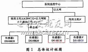
The overall design block diagram of this system is shown in Figure 1. The entire system uses a three-level structure, namely the hospital monitoring center, the ward host and temperature sensors. Among them, the host computer of the ward uses the single-chip AT89C52 as the main control unit, which mainly realizes network communication, temperature collection and display. Network communication is realized through the Ethernet to serial port module ZNE-100T developed by Zhou Ligong Company. Each ZNE-100T can be set with an IP address and a server IP address, which is convenient for forming a distributed temperature measurement network. The temperature measuring element adopts the digital temperature sensor DS18B20 produced by the American DALLAS semiconductor company. Each DS18 B20 has a unique ID number. It is small in size and can be packaged into the size of an ordinary thermometer. The maximum distance of its cable can reach 80 m, which is convenient for distributed placement On the patient. Temperature data can be scrolled and displayed on the LCD of the ward host. The network communication between the hospital monitoring center and each ward host adopts the CS architecture. The ward host sends each channel of temperature data to the hospital monitoring center every minute. The hospital monitoring center receives data from the host of each ward, can display the temperature change of each patient in real time in a curve or number, and performs abnormal processing and corresponding information recording, and synchronizes with the patient database to promptly remind the on-duty doctors and nurses to pay attention to the patient. .
2 Hardware design
2.1 Design of the single-chip microcomputer main control unit
The single-chip AT89C52 is a low-voltage, high-performance CMOS 8-bit single-chip microcomputer, which contains 8 KB of FLASH and 256 B of RAM. The chip has a built-in universal 8-bit central processor and has 32 bidirectional I / O ports. Among them, the P0 port of the single-chip microcomputer is used for the on-site display circuit. The dot matrix liquid crystal display module LM6038D can be used to scroll the temperature of each patient; the P1 port is used to connect the single-bus digital temperature sensor DS18B20; the P2 port is used for the field control circuit, including buttons, Indicator light, etc .; P3.0 (RXD) and P3.1 (TXD) of P3 port are used for serial communication with ZNE-100T. The system uses 5V power supply.
2.2 Single bus temperature acquisition circuit design
The measuring range of DS18B20 is -55 ~ + 125 ℃; when it is -10 ~ + 85 ℃, its accuracy is ± 0.625 ℃, and it can reach 0.1 ℃ through special treatment.
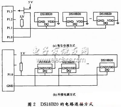
There are two main circuit connection modes of the single bus digital temperature sensor DS18B20, as shown in Figure 2. The design uses an external power supply, as shown in Figure 2 (b). In theory, each port of the microcontroller can be connected to countless DS18B20, but the load capacity of the microcontroller port is limited, and each port of the P1 port (P1.0 to P1.7) can only drive 8 DS18B20. In this design, only eight DS18B20s were connected using the P1.0 port.
2.3 Ethernet communication circuit design
ZNE-100T uses RS 232 interface (DB9 connector) to communicate with the single chip microcomputer, and the single chip microcomputer can only use TTL level. Therefore, an RS 232 conversion circuit must be designed to communicate with it. The RS 232 conversion chip selects MAX232E of Maxim Company. Its conversion circuit is shown in Figure 3.

2.4 LCD display circuit design
The liquid crystal display module adopts the LM6038D dot matrix liquid crystal module produced by Tuopu Micro. The module has 128 (column) & TImes; 64 (row) pixels. In addition, each column is designed with 4 more pixels, actually 132 & TImes; 64 Pixels, divided into 9 pages. The design makes full use of the extra 4 pixels to make a scroll bar, and the scroll bar can be operated by pressing the buttons, so that the user can turn the page to view the displayed content.
2.5 Control circuit design
The design has designed two buttons, which are respectively connected to the P2.0 and P2.1 pins of the single-chip microcomputer, and used to control the up and down of the scroll bar of the LCD screen. Two indicator lights are also designed, which are respectively connected to the P2.2 and P2.3 pins of the microcontroller, and are used to indicate the sending data indication (red light-emitting diode) and the network success indication (green light-emitting diode).
2.6 Watchdog circuit design
In order to prevent the system from looping and improve the reliability of the system, the MAX813L watchdog circuit is used. The maximum timeout is 1.6 s, high level reset, that is, a reset signal is sent after the RESET pin remains in the state for 1.6 s. Therefore, the RESET state must be changed once every 1.6 s in the program.
3 SCM programming
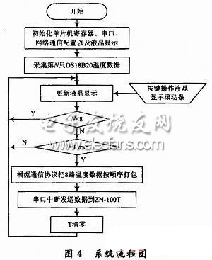
The single chip program of this system is written in C language. The program first initializes the hardware, including the initialization of the microcontroller AT89C52 register, the initialization of the internal RAM of the DS18B20, the initialization of the LCD display module LM6038D, and the initialization of the Ethernet communication module ZNE-100T. The program collects the temperature readings of 8 DS18B20s in turn through the time-sharing method and displays them on the LCD in real time. The user can turn the page to view the temperature data of the 8 DS18B20s by operating the button. The single chip microcomputer packages 8 channels of temperature data every 1min and sends Give ZNE-100T, ZNE-100T, real-time transmission of data to the hospital monitoring center. The system flow chart is shown in Figure 4. The main subroutines are: DS18B20 driver, LCD display driver and serial port and network communication driver.
speaker driver used in the helmet,Helmet Speaker,40Mm Helmet Speaker,32Ohm Helmet Speaker,Motorcycle Helmet Speaker
Helmet Speaker
Helmet Speaker,40Mm Helmet Speaker,32Ohm Helmet Speaker,Motorcycle Helmet Speaker
Shenzhen Xuanda Electronics Co., Ltd. , https://www.xdecspeaker.com