This article analyzes and studies the AC load line of the common-emitter-connected amplifier circuit in the resistance-capacitance coupling, transformer coupling, and direct coupling modes that reflect the output characteristics of the amplifier circuit. The characteristics of the AC load line, and the AC load line equation of the transformer-coupled amplifier circuit is deduced.
1 AC load line and its equation form
The relationship between the voltage drop of the transistor tube â–³ uce and the collector current â–³ ic through the AC equivalent load R'L when the amplifying circuit works together with the AC signal source and the DC signal power â–³ ic = f (â–³ uce) describes the AC The trajectory of the dynamic operating point after the signal is input. This straight line is called the AC load line.
It is known from literature [8] that the output ends of the AC path of the common-emitter amplifier circuit of resistance-capacitance coupling, transformer coupling and direct coupling are all in the form shown in Fig. 1. The relationship between AC voltage and current at the output is:
For resistance-capacitance coupling and direct coupling, the collector load is the parallel value of Rc and RL, ie R'L = Rc // RL. For transformer coupling, the collector load is R'L = n2RL, where n is the transformer ratio.
Substituting the relationship between AC quantity, DC quantity and total instantaneous quantity â–³ ic = "I" c + ic, â–³ uce = Uce + uce into equation (1) gives:
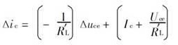
Equation (2) represents a straight line passing through the Q point with a slope of-1 / R'L, which is the AC load line equation of the amplifier circuit. The intercept of the equation on the vertical axis is I c + Uce / R'L, and the intercept on the horizontal axis is Uce + I cR'L. If V '= Uce + I cR' L, the intercept on the vertical axis and horizontal axis can also be expressed as V '/ R'L and V', which is the same as the DC load line on the vertical axis and horizontal axis. The form of the intercept is exactly the same.
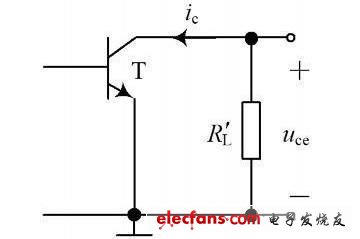
Figure 1 The output part of the AC path of the amplifying circuit under three coupling modes
2 Characteristics of AC load line under three coupling modes
2. 1 RC coupling amplifier circuit
The output parts of the resistance-capacitance coupling, common-emitter amplifier circuit and AC channel are shown in Figure 2 (a) and Figure 2 (b). The DC load line equation is:
The relationship between AC voltage and current at the output is shown in equation (1). The equations (3) and (1) are arranged to obtain the AC load line equation, as shown in equation (2).
From formula (3) and formula (2), DC load line and AC load line can be drawn, as shown in Figure 2 (b). It can be seen from the figure that the slope of the DC load line and the AC load line of the directly coupled amplifier circuit are different, and the AC load line is steeper.
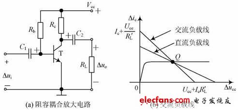
Figure 2 RC coupling amplifier circuit and AC load line
MAINTEX is a professional development and production of Pm stepper motor & permanent magnet stepper motor manufacturer and supplier in China. Welcome to contact us for PM stepper motor of your demands.
If you want PM Stepper Motor , Permanent Magnet Stepper Motor or Other Products , please contact us to customize for you.
Permanent magnet stepper motor
PM stepper motor,permanent magnet stepper motor
Shenzhen Maintex Intelligent Control Co., Ltd. , https://www.maintexmotor.com