With the expansion of the scale of the communication network, the centralized power supply of the communication power supply has gradually shifted to the decentralized power supply. On the other hand, from the perspective of downsizing and efficiency gains, the communication bureau (station) is required to achieve fewer people and unattended duties. Under such circumstances, to provide safe and reliable power supply to large-scale communication networks and ensure uninterrupted communication, it is necessary to conduct more scientific and standardized management of power supply equipment. The implementation of a remote monitoring system for communication power supplies provides an effective means for achieving the above goals. Original location
The purpose of the remote monitoring system for communication power supply is to conduct real-time networked monitoring of the high and low voltage distribution equipment, switching power supply, UPS and other communication power supply equipment, power supply, air conditioning, and environment of the scattered various offices (stations), and realize the manual method Unavailable 24-hour automatic patrol without interruption, automatic alarm when a fault occurs, on-duty personnel can monitor the operation status of power supply equipment in real time in the monitoring center, thereby changing the power supply maintenance from passive and decentralized manual round robin maintenance to centralized monitoring , Centralized maintenance, centralized management, reduce maintenance intensity and improve maintenance quality.
1 Remote monitoring system solution
The remote monitoring system for communication power is divided into two levels, which consists of the monitoring front desk (monitoring station) and the background (monitoring center), and transmits information through the PSTN (public telephone exchange network), as shown in Figure 1. The monitoring front desk has the function of monitoring each communication power supply and each environmental quantity, and transmits the collected data to the background in real time. The monitoring center is a centralized operation and maintenance center with multiple front desks, consisting of monitoring host hardware and monitoring software.
The monitoring center needs to configure two modems, one of which is a real-time modem, which is used to collect real-time data of the power supply equipment at the front desk, set the operating parameters of the power supply equipment and perform remote control operations, etc .; the other serves as an alarm modem when a controlled terminal When the power supply of the bureau generates an alarm, if the end office does not currently communicate with the monitoring system through real-time Moctern, the power monitoring front desk will dial the alarm Modem of the monitoring center and use it to transmit the alarm information of the failed power supply to remind the main control The room operators responded promptly to the on-site problems in a timely manner to reduce the losses to a minimum. The monitoring front desk of the power supply equipment of each controlled central office only needs to configure a Modem, which is used to transmit data and alarm information to the monitoring center. When the amount of data is not large and the frequency of communication data is not high, the use of a modem (Modem) and the use of telephone lines for data transmission is a very reliable method, and the cheap initial investment cost is also the advantage of the program.
2 Monitoring Center
The monitoring center hardware adopts a desktop computer with standard configuration, and connects two modems through two serial ports (if the number of serial ports is not enough, it can be expanded through PCI card). The software is designed with Visual C ++ language and includes functions such as user interface, communication, data processing, display, file (or database) management, etc. The monitoring software of the monitoring center dials in turn through the real-time Modem to the power supply front desk of the controlled central office. Once the modem dials successfully, a dynamic data path is established from the monitoring center to the remote on-site monitoring station, so that the monitoring center and the monitoring station can be realized. Two-way data transmission.
3 Modem communication
The digital signals that can be processed by the computer cannot directly enter the analog telephone line, and the conversion between the digital signal to the analog signal and the analog signal to the digital signal must be realized through the Modem. Modem status can be divided into command status and online status. Except for a short time for dialing, Modem is always in one of these states. When the Modem is powered on, it is in the command state first, and then enters the online state after the connection is successful.
In the command state, Modem does not communicate with the remote system, but accepts commands from DTE equipment in the form of Hayes standard AT commands. Whenever the PC (or microcontroller) sends an AT command, the Modem returns at least one result code to indicate whether the current execution is correct and the execution result. When the handshake between the two parties is completed and the communication link is established, the modem can send and receive data. At this time, the state of the modem is called the online state. In this state, the Modem communicates with the remote system. At this time, the Modem no longer attempts to interpret the data sent to him, but directly sends it out. When disconnecting, the system first sends the "+++" command to switch the modem from the online state to the command state, and then sends "ATH0" to hang up the modem.
4 Information collection content
The information collection of communication power includes three aspects:
(1) Operating parameters, such as AC input voltage alarm upper limit, AC input voltage alarm lower limit, ambient temperature alarm upper limit, ambient humidity alarm upper limit, battery temperature alarm upper limit, AC current transformer parameters, system DC output voltage alarm upper limit, system DC output Voltage alarm lower limit, rectifier current limit point, rectifier float charging voltage, rectifier equalizing charging voltage, rectifier shutdown temperature, rectifier shutdown voltage, battery pack low voltage warning threshold, battery pack protection voltage warning threshold, etc. In addition to collecting these actual operating parameters, the monitoring center can also change (or reset) these parameters remotely.
(2) Real-time data, such as the output current of each rectifier, the temperature of the main radiator of the rectifier, the running state of the rectifier fan, the AC input voltage and current, the system DC output voltage and current, the ambient temperature of the equipment room, etc.
(3) Alarm information, such as rectifier fan failure, rectifier main radiator temperature is too high, rectifier output over-voltage shutdown, rectifier temperature is too high shutdown; AC input phase loss, AC input voltage is too high, AC input voltage is too low, AC power failure , DC output short circuit, DC output abnormality, rectifier 485 communication interruption, etc.
5 Front desk monitoring system hardware design
The hardware block diagram of the front-end monitoring system is shown in Figure 2. The system uses the 8031 ​​microcontroller as the core, the human-machine interface uses LCD display, and has an operation keyboard. The watchdog uses ADM706 to improve system reliability. The clock chip uses MC146818 to record the time when real-time data or alarm information is generated. The program memory uses 27C512 EPROM, the limited Chinese character stock used by the system is placed at the high-end address of 27C512, and the data memory uses two 62256 SRAMs and one 2864E2PROM. 2864 is an electric erasable, non-volatile memory used to save the operating parameters of the system. This parameter can be set at the front desk via the keyboard or remotely through the monitoring center. The MAX487 is used to extend a 485 interface for communication with AC power distribution cabinets, DC power distribution cabinets, rectifier modules, and other environmental equipment. Sensors for data collection are placed in relatively independent intelligent devices such as AC power distribution cabinets, DC power distribution cabinets, and rectifiers. Adopt programmable universal asynchronous communication interface chip 16C550 and level conversion chip MAX214 to expand an RS 232 port, used to connect Modem.
6 Front desk monitoring system software design
The front-end monitoring system software is designed using C51 language. The main functions completed are man-machine interface design, 485 communication to obtain real-time data of smart devices, power system operating parameter settings, and modem-based remote communication to transmit real-time data and alarm information to the monitoring center. Mainly elaborate 16C550's control of Moctem and the realization method of remote communication.
Programmable universal asynchronous communication interface chip 16C550 has Modem control function, he has 5 interrupt sources, its priority is from high to low: receiving line status interrupt, receiving data ready interrupt, receiving data timeout interrupt, sending holding register empty interrupt Interrupted with Modem status. The 16C550 internal registers used in Modem communication mainly include:
(1) Data receiving register (RHR, read-only), address 0x00, register the received character.
(2) Send holding register (THR, write only), address 0x00, register the character to be sent.
(3) Interrupt flag register (ISR, read-only), address 0x02, used to determine what kind of interrupt is currently generated.
(4) Modem control register (MCR, readable and writable), address 0x04, through this register to realize the control operation of Modem.
(5) Communication line status register (LSR, read-only), address 0x05, he provides CPU with status information related to data transfer.
(6) Modem status register (MSR, read-only), address 0x06, provides Modem working status.
The dialer module for Modem is as follows:
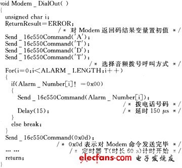
After dialing, receive data (or return code) through the interrupt service program of 16C550. If the Modem is in the online state and receives the data, this data is the data transmitted by the monitoring center; if the Modem is in the command state and receives the data, this data is the Modem's return code. Determine the return code of the dial command during the timer T timing. If the Return Code is ReturnConnect, it indicates that the connection is successful (the Modem is online) and data can be sent. Otherwise, the Modem should be hung up, and the timer T will stop and clear and then dial .
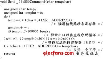
In the above dialer module, the function Send 16c550Command () is to send an AT command character to the Modem, the function body content is as follows:
7 Conclusion
The remote monitoring system of communication power supply based on Modem and public telephone network greatly saves the cost of constructing the network. Through practical use, the system works reliably, is easy to operate, and can meet the requirements of use. Its fast and real-time information transmission enables the concept of unmanned operation stations to be realized. The communication power supply site no longer needs the on-duty staff to inspect each device, achieving cost savings, shortening query time, and providing system operation efficiency.
Gaming Headset /Gaming Headset With Microphone /Stereo Gaming Headset /USB Gaming Headphones
Features:
1. Popular gaming headset with custom logo with different color
2. Manufacture with competitive price & good quality
3. Excellent sound performance
4. Material:PVC
5. Custom packing design service
6.Use for Fashion Show and Internet bar

Gaming Headset
Gaming Headset,Amazing Gaming Headsets,Gaming Headset Ps4,Gaming Headset Usb
Shenzhen Greater Industry Co., Ltd. , https://www.szgreater.net