Design of Motion Data Acquisition and Transmission Based on ZigBee Module
ADIS16355 of ADl Company provides complete three-axis inertial detection (angular motion and linear motion). The core adopts iMEMS sensor technology and a built-in embedded processor for sensor calibration and tuning; SPI interface is used for easy connection and programming; with ± 10 g test range, ambient temperature between -40 ~ + 85 ℃; programmable power control capability And programmable filter design; ultra-small module size, widely used. Use ARM7 microprocessor LPC2148 to collect the data and store it in the SD card for subsequent data transmission. The system is very widely used and can be used as a data collection and analysis system for the rehabilitation of patients in the medical field, as well as a data collection, analysis and control system for sports equipment.
1 Overall system design
1.1 System architecture
The structure of the entire data acquisition and transmission system is shown in Figure 1. LPC2148 is used to control ADIS16355 and is responsible for sending the collected data to the SD card. While storing the data, it can be sent wirelessly by ZigBee module and sent to the client for processing. At the receiving end, you can use the client platform to observe and process the collected data; you can also remove the SD card and put it on the PC for analysis. 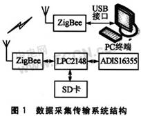
1.2 Circuit design
The whole design is divided into 3 parts: ADIS16355 data acquisition, ZigBee data transmission, SD card data storage.
(1) Data acquisition and transmission circuit
The circuit connection is shown in Figure 2. ADIS16355 provides SPI interface, which is mainly composed of 4 pins: SCLK0, MOSI0, MISO0 and SSEL0. Among them SCLK0 is the common clock pin of the whole SPI bus, MOSI0, MISO0 are the input and output pins of the master and slave. SSEL0 is the flag pin of the slave. For the two SPI bus devices that communicate with each other, the low level of the SSEL0 pin is the slave, and the high level is the master. 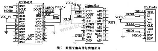
The sending module adopts ZigBee module. In the data transmission interface circuit, it provides a universal asynchronous transceiver mode (UART), which mainly includes RXD1, TXD1, and DTR1. RXDl is the data transmission, TXDl is the data reception; DTR1 is the control of the ZigBee module, you can control the power of the ZigBee module through the main control chip LPC2148 to control the power of the ZigBee module. In sleep mode.
(2) Memory circuit
Considering the convenience of the system and the need for large data storage and low power consumption, the SD card was selected. The SD card has two interface protocol modes, namely SD mode and SPI mode, and the definition of each pin is different in different modes. In the specific communication, the host LPC2148 can only select one communication mode, the card will automatically detect the mode of the reset command, and will communicate in accordance with this communication mode in future communications.
LPC2148 comes with hardware interface SPI, so it is very convenient to use SPI interface to access the card. In the circuit design of Figure 3, four lines are given. SSEL1 is the chip select signal sent by the host LPC2148 to the card, MOSI1 is the unidirectional data signal sent by the host to the card, SCLK1 is the clock signal sent by the host to the card, and MISO1 is The unidirectional data signal sent by the card to the host.
1.3 Power consumption considerations in system design
In terms of data acquisition and transmission, it is required to be easy to use and work for a long time, so a rechargeable battery is used in power supply, which puts a requirement on the power consumption of the system, that is, it must be low power consumption, so that the system can be as long as Work continuously for months. LPC2148 uses a 32-bit high-speed processor with reduced instructions. The power supply voltage is 3.3 V and the core voltage is 2.5 V. The chip power consumption is relatively low.
Both the sensor module ADIS16355 and the ZigBee transmission module have programmable power consumption control. By setting the register data, they can be put into sleep mode in standby mode to fully meet the system design requirements. After testing, the system can work continuously for 4 to 5 months under the power supply condition of 1 300 mAh with a self-made rechargeable 7 V battery.
2 Software design
The system software design is mainly divided into 3 parts: SD card reading and writing, sensor data acquisition, ZigBee data receiving and sending, and the flow of the program is shown in Figure 3. For the firmware program development, Keil uVision3 is used to complete, and then use Keil ULINK2 emulator to download and debug. 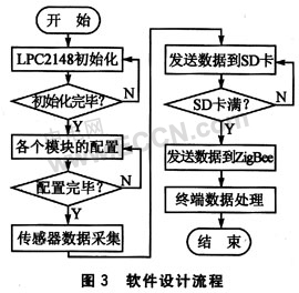
Here are some realization procedures of the data acquisition of the three-axis sensor ADIS16355: 
3 Performance test
This set of data acquisition equipment uses a wireless ZigBee transmission module to form a self-organizing network, and the measured maximum barrier-free communication distance can reach about 400 m.
Robot Vacuum Cleaners With Mopping
Robot Vacuum Cleaners With Moppin,Robot Vacuum Cleaner With Bluetooth ,Robot Vacuum Cleaner With Gyroscope,Cleaner Robot Ultrasonic Cleaner
NingBo CaiNiao Intelligent Technology Co., LTD , https://www.intelligentnewbot.com