introduction
This three-part series focuses on how to accurately estimate the jitter of a clock source and combine it with the aperture jitter of the ADC. In this part, Part 2, this combined jitter will be used to calculate the signal-to-noise ratio (SNR) of the ADC, which is then compared to the actual measurement.
Filtered sampling clock measurement
We did a test to check the match between the measured clock phase noise and the clock jitter extracted from the measured SNR of the ADC. As shown in Figure 11, a TI CDCE72010 using the Toyocom 491.52-MHz VCXO was used to generate the 122.88-MHz sampling clock, and we used Agilent's E5052A to measure the filtered phase noise output. Two different TI data converters (ADS54RF63 and ADS5483) were evaluated with an input frequency whose SNR was primarily limited by the sampling clock jitter. The size of the Fast Fourier Transform (FFT) is 131000 points.
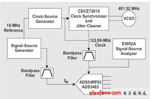
Figure 11 Structure of the filtered clock correlation test device
The graph shown in Figure 12 depicts the measured output phase noise of the filtered CDCE72010 LVCMOS output. The 131000 point FFT size sets the low integration bandwidth to ~500 Hz. The upper limit of the integration is set by the bandpass filter and its effect is clearly visible in the phase noise plot. The phase noise beyond the limit of the bandpass filter shown in the graph is the noise floor of the E5052A and should not be included in the jitter calculation. The integration of the filtered phase noise output results in a clock jitter of ~90 fs.
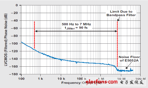
Figure 12 measured phase noise of the filtered clock
Next, we built a thermal noise baseline. We directly sampled the two ADCs from the ~35 fs jittered clock source generator using the filtered sample clock, and the CDCE72010 was bypassed. Setting the input frequency to 10MHz is expected to have no effect on the clock jitter SNR. Then, the aperture jitter of each ADC is determined by increasing the input frequency to a frequency at which the SNR is primarily jitter limited. Since the sample clock jitter is much lower than the estimated ADC aperture jitter, the calculation should be very accurate. It is also important to note that the output amplitude of the clock source should increase (but not much beyond the maximum rating of the ADC), thereby increasing the slew rate of the clock signal until the SNR stabilizes.
We know that the external clock jitter of the clock source generator filtered output is ~35 fs, so we can use the measured SNR results and then solve the aperture for Equations 1, 2 and 3 in Part 1 (see Reference 1). The jitter value is calculated to calculate the ADC aperture jitter, see Equation 4 below. Table 3 lists the SNR results measured for each ADC and the calculated aperture jitter.
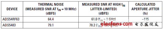
Table 3 measured SNR and calculated jitter
Using the ADC aperture jitter and the sampling clock jitter of the CDCE72010, the SNR of the ADC can be calculated and compared to the actual measurement. The ADC clock aperture jitter can be used to calculate the sampling clock jitter of the CDCE72010 from the measured SNR values, as listed in Table 4. At first glance, the SNR value is expected to be somewhat close to the measured value. However, when comparing the sampled clock jitter calculated by the two ADCs with the 90fs measured value, there is another different scenario with quite a few mismatches.
The reason for the mismatch is that the calculated aperture jitter is based on the fast conversion rate of the clock source generator. The CDCE72010's LVCMOS output eliminates the higher-order harmonics of the clock signal, which helps to form fast-rising edges. The waveform shown in Figure 13 shows the bandpass filter dramatically reducing the unfiltered LVCMOS output slew rate and converting the square wave to a sine wave.
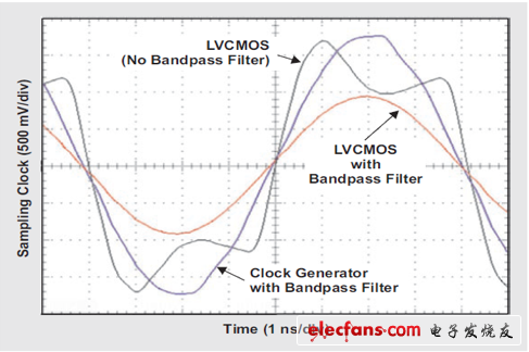
Figure 13 Effect of Clock Jitter on Sample Clock Conversion Rate
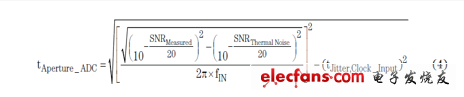
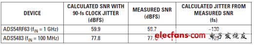
Table 4 SNR results of 90-fs clock jitter
ZOOKE provides you with safe and reliable connector products, with 2.54 spacing products providing more possibilities for limited space and creating more value for the research and development and production of terminal products.
2.54 wire to board connectors,2.54 connectors,ZOOKE connectors
Zooke Connectors Co., Ltd. , https://www.zookeconnector.com