Here is the circuit diagram of the U201 multimeter. This schematic provides a detailed view of the internal components and connections that make up the device, helping users understand its functionality and design. Whether you're a technician, hobbyist, or student, this diagram can serve as a useful reference for troubleshooting or learning about multimeter electronics.
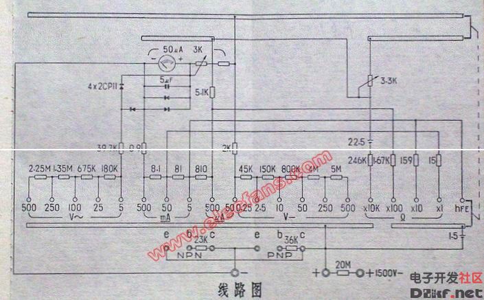
The U201 multimeter is known for its reliability and precision in measuring voltage, current, and resistance. The circuit layout shown here illustrates how different electronic parts such as resistors, capacitors, transistors, and integrated circuits are interconnected to perform these measurements accurately. Understanding this diagram can be particularly helpful if you're working on repairing or modifying the device. Always ensure proper safety measures are taken when handling electrical equipment. If you're interested in building your own multimeter or studying its inner workings, this diagram is an excellent starting point.
Contactor accessories are an important part of the contactors' working. It includes different kinds of models.
Our contactor accessories are mainly divided into the following series:
LA2-D Timer Delay Block
LA1-D Axuiliary Contact Block
F8 Side Mount Axiliary Contact Block
LA3-DN Auxiliary Contact Block
BA3-D Timer Delay Block
LX1-D Coil of Contactor
LX1-F Coil of Contactor
Auxiliary Switch,Auxiliary Contact Block,Contactor Block,Contactor Coil
Ningbo Bond Industrial Electric Co., Ltd. , https://www.bondelectro.com