1. Working principle The single-phase bridge rectifier circuit is the most basic circuit for converting AC to DC. The circuit is shown in Figure 10.1.2. 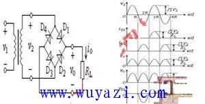
The pulsating voltage flowing through the load contains a DC component and an AC component, and the pulsating voltage can be subjected to Fourier analysis. At this time, the second harmonic amplitude in the harmonic component is the largest, and the ratio of the amplitude of the lowest harmonic to the average value is called the pulsation coefficient S. 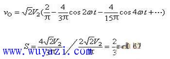
Figure 10.1.3 Load characteristic curve
ZGAR FILTER TIP
ZGAR electronic cigarette uses high-tech R&D, food grade disposable pod device and high-quality raw material. All package designs are Original IP. Our designer team is from Hong Kong. We have very high requirements for product quality, flavors taste and packaging design. The E-liquid is imported, materials are food grade, and assembly plant is medical-grade dust-free workshops.
Our products include disposable e-cigarettes, rechargeable e-cigarettes, rechargreable disposable vape pen, and various of flavors of cigarette cartridges. From 600puffs to 5000puffs, ZGAR bar Disposable offer high-tech R&D, E-cigarette improves battery capacity, We offer various of flavors and support customization. And printing designs can be customized. We have our own professional team and competitive quotations for any OEM or ODM works.
We supply OEM rechargeable disposable vape pen,OEM disposable electronic cigarette,ODM disposable vape pen,ODM disposable electronic cigarette,OEM/ODM vape pen e-cigarette,OEM/ODM atomizer device.

Vape Filter Tip,Disposable Pod Vape,Disposable Vape Pen,Disposable E-Cigarette,Electronic Cigarette,OEM vape pen,OEM electronic cigarette.
ZGAR INTERNATIONAL TRADING CO., LTD. , https://www.zgarpods.com