Experiment PLC elevator control system
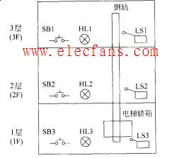
Schematic diagram of the three-story elevator work Explanation: This experiment is a comprehensive experiment, which requires students to design the actual operation of the elevator operation, and design the I / O interface according to the operation requirements. The indicator lights can be connected to simulate the elevator movement. This experiment can also be completed in the experiment area of ​​the elevator control system of the experiment box. The reference scheme is given below.
1. The purpose of the experiment
1. Through the simulation of engineering examples, master the programming and program testing methods of PLC.
2. Be more familiar with PLC I / O connection.
3. Familiar with the programming method of automatic control of the three-story elevator.
2. Control requirements Experiment content Complete the automatic control of the three-story elevator. The elevator is driven by a motor up and down: the elevator goes up when the motor rotates forward; the elevator goes down when the motor reverses.
Each floor is equipped with call buttons SB1, SB2, SB3, call indicator lights HL1, HL2, HL3 and in-position travel switches LS1, LS2 and LS3.
The elevator only responds to ascending calls during ascent, and only responds to descending calls during descending. Any call in the opposite direction is invalid.
When the call is responded to, the call indicator on the call floor lights up, and the indicator goes off when the elevator reaches the call floor; when the call is invalid, the call indicator light does not light up. The automatic control requirements for the three-story elevator are as follows:
(1) When the elevator stops at 1F or 2F, if you press the 3F button to call, the elevator will rise to 3F and stop by the limit switch LS3;
(2) When the elevator stops at 3F or 2F, if you press the 1F button to call, the elevator will descend to 1F and stop by the limit switch LS1;
(3) When the elevator stops at 1F, if you press the 2F button to call, the elevator will rise to 2F and stop by the limit switch LS2;
(4) When the elevator stops at 3F, if you press the 2F button to call, the elevator will descend to 2F and stop by the limit switch LS2;
(5) When the elevator stops at 2F, and the 2F and 3F buttons are called, the elevator first rises to 2F, after being suspended by LS2 for 2S, it continues to rise to 3F and stops by LS3;
(6) When the elevator stops at 3F, and the 1F and 2F buttons are called, the elevator descends to 2F, after being suspended by LS2 for 2S, it continues to descend to 1F and stops by LS1;
(7) While the elevator is ascending, any down button call in the opposite direction is invalid;
(8) While the elevator is descending, any upward button call in the opposite direction is invalid;
(9) The arrival time between each floor should be completed within 10s, otherwise the elevator will stop;
(10) The starting position of the elevator and the start and stop of the program are designed by themselves;
(11) Once the fault signal appears, it will immediately stop and alarm.
In addition, the following functions are added according to time selection:
Design elevator alarm system;
3. Preparation of experimental programs (instruction list and ladder diagram)
4. Experimental report (1) Draw the configuration diagram of the PLC system used (PLC system wiring diagram);
(2) Write out the I / O address and I / O definition of the PLC used;
(3) Write ladder program or mnemonic symbol program (the source program should be marked), debug and run the program correctly.
Recommend: PLC control four-story elevator and control system program PLC control three-story elevator automatic operation example wiring schematic
Custom Wire Harness Assembly
- Electrified dimensional build boards with 100% continuity test
- Capabilities to test for fuse,diode,resistor, and relay presence
- Mating test fixtures for lower production wire harnesses
- Ability to free hand build harnesses for prototypes and design validation
- Separate layout boards for addition of fir tree clips, rosebuds, clamps,and labels after coverings added
- Capabilities to add board interlocks and test markings to harness as needed
Custom Wiring Harness,Wiring Harness,Cable Assemblies,Wire Harness,Wire Harness Assembly Manufacturer
ETOP WIREHARNESS LIMITED , https://www.oemmoldedcables.com