We decompose the designed data acquisition system into three parts: the data acquisition part, the data communication part, and the data processing part.
The data acquisition part should include: A/D converter, timing, mode control, data buffering. It should be able to accept commands from the host, control the A/D converter to collect data according to different modes, temporarily store it in the data buffer, and then send it to the host according to the host command. This part of the function is implemented by a single chip and interface is the best way.
The data communication part should include: simple, efficient, universal data communication mode and hardware and software support. It should be able to achieve the best connection and communication between data acquisition and data processing. Because USB is an external bus standard, it is used to regulate the connection and communication between the computer and external devices, and has the advantages of fast transmission speed, convenient use, hot plugging, flexible connection, independent power supply, etc., so this part adopts USB interface. The connection is best. [1]
The data processing part should include: a powerful, efficient, versatile, and adaptable software and hardware support platform. It should be able to perform two major functions of master control and data processing. The main control is to give commands to the data collection part according to the user's needs, collect data, manage the data communication part at the same time, realize the uploading of information, and read the data. Data processing is to provide convenient and practical data analysis, processing, storage, display, output and other application functions to meet the user's needs. This part of the function is naturally not a PC.
The system function arrangement is: PC as the host (also called the upper computer), the single chip (also called the lower computer) is responsible for data acquisition and buffer storage, and the USB interface is responsible for data communication between the two.
The specific work flow is: the PC receives the user's application command, configures the data acquisition parameters according to the system function, sends a control command to the single-chip microcomputer through the USB interface, and the MCU presses the command to control the A/D conversion for data acquisition, and the collected data is collected. The data is buffered and saved. After collecting a batch of data, it is sent to the PC through the USB interface according to the requirements of the host. The PC completes the basic applications of data storage, simple analysis, processing, display, and output. Further, the data can be formatted for input by other professional data processing software to achieve more advanced data processing functions.
MCU selection
To meet design requirements, the microprocessor must contain two basic modules with A/D conversion and USB communication capabilities, as well as other modules that implement extended functionality.
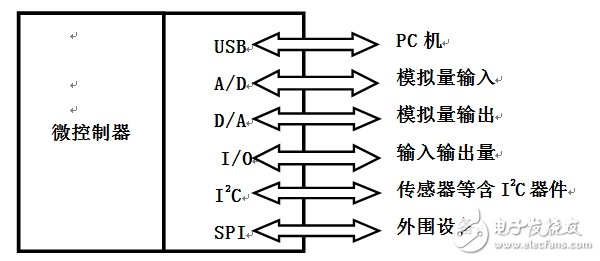
The figure above shows the envisioned function board diagram. The controller communicates with the peripheral device through its function module: USB module is connected with PC for USB communication; A/D module is connected with analog input for A/D conversion; The D/A module is connected to the analog output to generate the output waveform; the I/O interface is externally connected to the input and output; the I2C module is connected to the I2C-containing device such as the sensor for I2C communication; the SPI module is connected to the peripheral device to make the MCU and various peripheral devices Communicate in a serial manner to exchange information.
There are two kinds of data acquisition schemes for the USB bus, one is to use a dedicated USB communication chip. The other is to use a microcontroller with a USB interface function. Considering the actual situation, this design uses the second option.
PIC18F4550 is an 8-bit high-end single-chip microcomputer with full-speed USB interface produced by Microchip. The MCU has the features of reduced instruction set and Harvard structure, and it has fast running speed and high execution efficiency. Its hardware resources are very rich, and integrated with multiple functional modules: ICSP interface module, can communicate with the PC through PICkitTM 3, program programming and debugging; its full-speed USB 2.0 interface module can be convenient and fast Implement USB communication. [3]
Therefore, we chose PIC18F4550 microcontroller for design. Its advantages are:
1, with its USB interface, you can achieve communication with the PC, no need to add a USB interface chip.
2, using its ICSP module, you can achieve direct programming of the PC to the microcontroller, and online debugging.
3, can make the design of the circuit more concise and practical, not only improve the safety and reliability of the entire design, but also reduce the power consumption of the entire system.
4, Microchip provides integrated development environment Mplab and assembly language, C language compiler, making us easier, more convenient and faster in program debugging, simulation operation. Microchip also provides examples of USB communications and demo subroutines that make it easier and faster to use USB communications.
What is a high frequency PCB?
What is a PCB high frequency board? Special circuit boards with higher electromagnetic frequencies. Generally speaking, high-frequency boards can be defined as printed circuit boards with frequencies above 1GHz. Its various physical properties, precision, and technical parameters require very high requirements, and are often used in communication systems, automobile anti-collision systems, satellite systems, radio systems and other fields.

1. The thermal expansion coefficient of the high-frequency circuit board base material and copper foil must be the same. If they are inconsistent, it will cause the copper foil to separate during the hot and cold changes.
2. The high-frequency circuit board substrate should have low water absorption, and high water absorption will cause dielectric constant and dielectric loss when wet.

4. The dielectric loss (Df) of the high-frequency circuit board substrate material must be small, which mainly affects the quality of signal transmission. The smaller the dielectric loss, the smaller the signal loss.

High Frequency Board,Multi-Wiring Printed Board,Ceramics Base Copper-Clad Laminates,Ro4350B+Fr4 Hybrid Board
HAODA ELECTRONIC CO.,LIMITED , https://www.pcbhdi.com