Diodes are one of the most common devices in electronic design. Depending on the application, engineers pay more attention to the type of diode, forward current, reverse withstand voltage and switching time. Relatively speaking, the power dissipation (Power DissipaTIon) is equally important.
It is well known that diodes have a single wire conductivity. According to the semiconductor material, it is divided into a silicon diode and a germanium diode; according to the application, it is divided into a rectifier diode, a detection diode, a switching diode and a Zener diode.
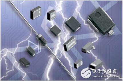
Figure 1 Common Diodes
For some applications, such as power rectification, the problem of dissipated power needs to be considered. Definition of dissipated power: The difference between the total power of the active component input and the total output of the active output at a certain time. Under linear conditions, the conduction power dissipation calculation is relatively simple, PD=I2R, or PD=U2/R. In the switch state, the calculation is relatively complicated.
The dissipated power of the diode is related to the allowable junction temperature. The maximum junction temperature allowed by the silicon diode is 150 °C, while the maximum allowable junction temperature is 85 °C. The semiconductor operating temperature is limited. When the actual power is increased, the node temperature will also become larger. When the node temperature reaches 150 °C, the power at this time is the maximum dissipated power. Of course, the power dissipated has a certain relationship with the package size. Generally, the device with a large package has a relatively large maximum power dissipation. The most common one is that the high-power device has a large volume and a large area of ​​heat dissipation metal surface.
The power dissipation of a particular type of diode is related to test conditions, such as test ambient temperature and thermal conditions. Normally, the maximum power dissipation tested is at 25 °C. As the ambient temperature increases, its maximum dissipated power will decrease because the thermal conduction temperature difference under this condition becomes smaller. For example, at 25 ° C, a diode can dissipate 1 W, and at 75 ° C, consume The power dissipation may become 0.4W. The maximum dissipated power is allowed to be related to the heat dissipation condition. The better the heat dissipation condition is, the higher the dissipated power is. The dissipated power is 1W at the same ambient temperature. After the heat sink is added, the dissipated power may become 1.7W.
One parameter that characterizes heat dissipation is thermal resistance. Thermal resistance reflects a comprehensive parameter that prevents heat transfer. The thermal resistance is similar to the resistance in electronics, and is a reference that reflects the size of the "blocking ability." The smaller the thermal resistance, the stronger the heat transfer capability; conversely, the larger the thermal resistance, the smaller the heat transfer capability. From an analogy point of view, heat is equivalent to current, the temperature difference is equivalent to voltage, and the thermal resistance is equivalent to resistance. Among them, the thermal resistance Rja: the total thermal resistance of the heat source of the chip to the surrounding cooling air, the unit is °C / W, indicating the temperature difference between the two ends of the heat conduction at 1W.
Take the 1N4448HWS as an example. Check the phone manual to see its thermal characteristics as follows:
Figure 2 Thermal characteristics parameters
It can be seen that its dissipated power PD=200mW and thermal resistance is 625°C/W, of which the two quantities are ambient temperature 25°C, and the solder is tested under FR-4 material PCB condition, as described in the manual Part mounted on FR- 4 PC board with recommended layout.
The dissipated power is related to the ambient temperature. The higher the temperature, the smaller the dissipated power. The relationship between the 1N4448HWS dissipated power and the ambient temperature is as follows:
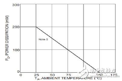
Figure 3 Relationship between dissipated power and ambient temperature
At 0 to 25 ° C, the power dissipation is constant at 200 mW. At 25 to 150 ° C, the linearity decreases, reaching 150 ° C, and the power dissipation is 0. At this temperature, the silicon tube is no longer working. From this table, the thermal resistance can be calculated, and the linear part slope reciprocal ||=Rja=625°C/W. According to this table, PD=-(TA-25)+0.2, (TA-≥25) can be obtained. According to this formula, the maximum dissipated power at different ambient temperatures can be calculated.
During the design process, people pay more attention to the temperature at which the device works to ensure a safe working range. Taking 1N4448HWS as an example, when the ambient temperature is 25°C, the actual power is 100mW, the temperature is 25+625*0.1=87.5°C, which can work normally; when the actual power is 200mW, the temperature is 25+625. *0.2=150°C, at this time the maximum temperature of the temperature has been reached, which is dangerous and should be avoided.
In terms of heat transfer of diodes, PD and thermal resistance Rja are mainly considered. The former is the maximum power dissipation, and the actual work cannot exceed this value. The latter is the heat transfer resistance parameter, showing the heat transfer capability of different diodes. When using a diode, consider not only the forward current, the reverse withstand voltage, and the switching time, but also the power dissipation.
Sky Curtain Uno,Landscape Lighting Of Outdoor Buildings,Ip67 Led Cabinet Light,Led Light Aluminum Alloy
Kindwin Technology (H.K.) Limited , https://www.ktl-led.com