Recently, Xiao Bian interviewed Doug Bailey, a senior expert in LED driver circuit design. He summed up the problems that need to be paid attention to in the design work and personal experience. I would like to share the following conclusions:
First, do not use bipolar power devices
Doug Bailey pointed out that because bipolar power devices are cheaper than MOSFETs, generally about 2 cents, some designers use bipolar power devices to reduce the cost of LED driving, which will seriously affect the reliability of the circuit, because with LED As the temperature of the driver board increases, the effective working range of the bipolar device will shrink rapidly, which will cause the device to malfunction when the temperature rises, thus affecting the reliability of the LED lamp. The correct way is to select the MOSFET device and the service life of the MOSFET device. It is much longer than a bipolar device.
Second, try not to use electrolytic capacitors
Do you want to use electrolytic capacitors in the LED driver circuit? At present, there are supporters and opponents. Supporters believe that if the temperature of the board can be controlled well, the purpose of extending the life of the electrolytic capacitor can be achieved in turn. For example, a high-temperature electrolytic capacitor with a life of 105 degrees and a lifetime of 8000 hours is selected, according to the estimated life expectancy of the electrolytic capacitor. “Every time the temperature is lowered by 10 degrees, the life is doubledâ€, then it has a working life of 16,000 hours in a 95 degree environment, a working life of 32,000 hours in a 85 degree environment, and a working life of 64,000 hours in a 75 degree environment, if Lower operating temperature, longer life! From this point of view, as long as the choice of high-quality electrolytic capacitors has no effect on the life of the drive power!
Other proponents believe that the low-frequency flicker caused by the high ripple current caused by electroless capacitors will cause physiological discomfort to some people's eyes. The large amplitude of low-frequency ripple will also cause some digital camera equipment to appear poor. A brightly lit grid of flickering lights. Therefore, high-quality light source lamps still need electrolytic capacitors. However, opponents believe that electrolytic capacitors will naturally age. In addition, the temperature of LED lamps is extremely difficult to control, so the life of electrolytic capacitors will inevitably decrease, thus affecting the life of LED lamps.
In this regard, Doug Bailey believes that in the input part of the LED driver circuit can be considered without electrolytic capacitors, in fact, the PI LinkSwitch-PH can save electrolytic capacitors, PI's single-stage PFC / constant current design allows designers to save large capacity Capacitor, in the output circuit, high-voltage ceramic capacitors can be used instead of electrolytic capacitors to improve reliability. "Some people design a two-stage circuit, using a 400V electrolytic capacitor at the output, which will seriously affect the circuit. Reliability, it is recommended to use ceramic capacitors for single-stage circuits," he stressed. “For industrial applications that do not pay much attention to dimming, high temperature environments, and high reliability, I strongly recommend not using electrolytic capacitors for design.â€
Third, the MOSFET's withstand voltage should not be lower than 700V
MOSFETs with a withstand voltage of 600V are relatively cheap. Many people think that the input voltage of LED lamps is generally 220V, so the withstand voltage of 600V is enough, but in many cases the circuit voltage will reach 340V. In the case of surge, the 600V MOSFET is easily broken down. Therefore, the life of the LED lamp is affected. In fact, the selection of the 600V MOSFET may save some cost but the cost of the entire circuit board. Therefore, "Do not use a 600V withstand voltage MOSFET, and it is better to use a MOSFET with a withstand voltage exceeding 700V. He emphasized.
Fourth, try to use a single-stage architecture circuit
Doug said that some LED circuits use a two-stage architecture, the "PFC (Power Factor Correction) + Isolated DC / DC Converter" architecture, which will reduce the efficiency of the circuit. For example, if the efficiency of the PFC is 95% and the efficiency of the DC/DC section is 88%, the efficiency of the entire circuit will be reduced to 83.6%! "The LinkSwitch-PH device of PI will simultaneously have a PFC/CC controller, a 725VMOSFET and The MOSFET driver is integrated into a single package, increasing the efficiency of the driver circuit to 87%!†Doug points out, “This device greatly simplifies board layout and eliminates up to 25 components used in traditional isolated flyback designs. The components that are omitted include high-voltage large-capacity electrolytic capacitors and optocouplers.†Doug said that the LED two-stage architecture is suitable for older drivers that must use a second constant-current drive circuit to enable the PFC to drive LED constant current. These designs are outdated and no longer cost effective, so in most cases it is best to use a single stage design.
Fifth, try to use MOSFET devices
If the LED luminaires are not designed to be very powerful, Doug recommends using an LED driver with integrated MOSFETs because the benefit of this is that the integrated MOSFETs have less on-resistance and generate less heat than discrete, in addition to integrated MOSFETs. The controller and the FET are generally together, and generally have a thermal shutdown function. When the MOSFET overheats, the circuit is automatically turned off to protect the LED lamp. This is very important for the LED lamp, because the LED lamp is generally small and difficult to dissipate air. . "Sometimes LEDs can cause people to burn because of overheating, but our solution has never been like this," he said.
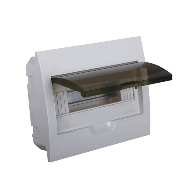
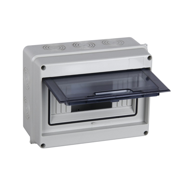
The distribution box is a massive parameter on the data. Generally, it constitutes a low-voltage forest. According to the electrical wiring, it is required to assemble the switchgear, measuring instrument, protective electrical appliance and auxiliary equipment in a closed or semi-closed metal cabinet or on the screen to form a low-voltage power distribution. box. The circuit can be switched on or off with a manual or automatic switch during normal operation.
Our company's Distribution Boxes are mainly divided into six series(as follow),had exported into global market for many years:
Universal Junction Boxes
Euro type Switch Boxes
Distribution Box
Locks for Switch Boxes
Industrial Plug and Socket
JXF Water Proof Metallic Panel Board


Distribution Boxes
Distribution Boxes,Terminal Box,Switch Box,Control Switch Box
Ningbo Bond Industrial Electric Co., Ltd. , https://www.bondelectro.com