Introduction to CMOS automotive electronic regulator based on single chip microcomputer
This article refers to the address: http://
The degree of automobile electronicization has become an important standard for the international measurement of the advanced level of automobiles. It is for this reason that the current automotive electronics industry is constantly evolving and the countries are competing for development, constantly applying high technology and improving the electrification performance of automobiles. In order to obtain a bigger market.
At present, the common problem of automobile voltage regulator is poor stability, short life, instability of the regulator will lead to instability of the generator input voltage, which will affect the power supply voltage of the vehicle's electrical equipment, which will greatly affect the normal operation of the vehicle circuit. It will also reduce the life of the electrical equipment, and the short life of the regulator will not only bring economic burden, but also adversely affect the stability of the generator output voltage.
The emergence of the monolithic CM0S automotive electronic regulator now reduces the size of the regulator so that it can be made with an alternator. The voltage regulator is designed as a monolithic CMOS integrated circuit, which not only improves the stability of the regulator, but also improves the power quality of the vehicle, effectively prolongs the service life of the automotive electronic equipment, and adapts to the current small size of the automotive alternator. And the development trend of large output power. At the same time, the design also adapts to the pursuit of the current regulator "high performance, multi-function, high power, long life".
1 circuit principle and structure
The block diagram of the car electronic regulator is shown in Figure 1.
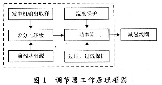
When the car starts to add the input voltage, the reference voltage source generates a reference voltage for use in the internal circuit; the error amplifier receives the output voltage signal; the overcurrent protection circuit samples the output current of the power tube; the thermal protection circuit checks the temperature of the circuit; the error is amplified, The flow safety zone protection and the overheat protection circuit are fed into the power tube. When only one abnormal phenomenon occurs, the adjustment tube will be turned off to adjust the voltage and protect the function.
2 circuit design
2.1 front-end reference source
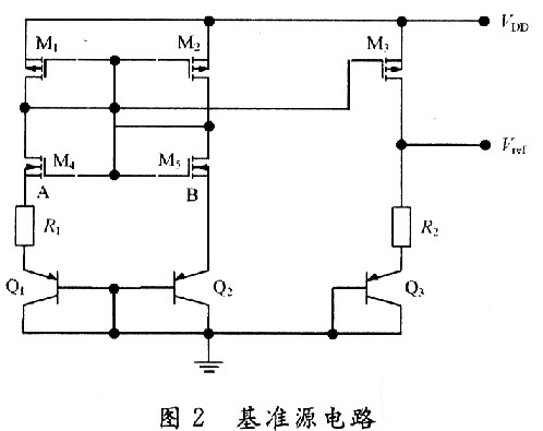
The front-end reference voltage source in the designed chip circuit is to provide a reference voltage that is stable to the power supply voltage and temperature to the subsequent differential comparison circuit, and then the differential comparison circuit compares it with the voltage sampled from the generator. A comparison is made to control the output of the generator, the circuit of which is shown in Figure 2. In Figure 2, M1, M2, and M5 form a mirror current source, so that the current flowing through the three tubes is equal, and both are I; M3 and M4 form a voltage clamping circuit, so that the voltages at points A and B are consistent. The mirror current source and the voltage clamping circuit together form a PTAT source, and its positive temperature coefficient is used to compensate the negative temperature coefficient of the PN junction, thereby obtaining a reference voltage that does not substantially change with temperature.
2.2 differential comparison circuit
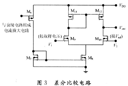
The function of the differential comparator stage is to compare the reference voltage from the front-end reference to the sampled voltage of the generator. When the generator output voltage is lower than 14V, the excitation current adjustment tube works normally, the excitation current flowing through the generator rotor winding rises rapidly, and the generator output voltage also rises rapidly. When the output voltage of the generator reaches 14V, the differential output voltage is sufficient to drive the subsequent control circuit to control the grounding of the excitation current regulating tube, and the gate current is divided, thereby reducing the excitation current of the generator moving coil, thereby reducing the generator. Output voltage to achieve voltage regulation. Its circuit is shown in Figure 3.
2.3 generator output voltage sampling circuit
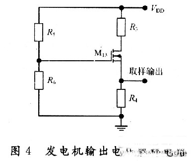
The function of the car regulator is to adjust the output voltage of the generator to control it near a certain value. Since the output voltage of the generator is to be controlled, the output of the generator needs to be sampled. There are two ways to sample the voltage of the electronic regulator, namely the output voltage of the sampling generator and the voltage of the sampling battery. In the separate device regulator, the double sampling method is mostly used. In this design, the front reference voltage source has provided an accurate comparison voltage, so the output voltage of the alternator can be sampled. The sampling circuit is shown in Figure 4. In Figure 4, resistors R5, R6 and M13 form an energy-saving circuit. When the car stops working, this part of the circuit cuts off the connection between the regulator circuit and the battery, thereby avoiding the loss of battery power.
2.4 temperature protection circuit
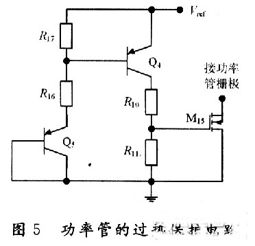
The power device handles high voltage and high current. High voltage and high current will cause the device temperature to rise. When the temperature is high to some extent, the device will be damaged by overheating. Therefore, the overheat protection circuit should be designed in the integrated circuit containing the power device. It is temperature protected. The temperature protection circuit of the power tube is shown in Figure 5. Since the temperature characteristics of the MOS device are good, the parameters (mainly the threshold voltage) vary little with temperature, so this part of the circuit is implemented by a PNP tube. In the circuit, the B and C poles of the Q5 tube are connected to form a PN junction, and the temperature of the power tube is detected. When the temperature of the power tube reaches the limit temperature (here, 150 ° C), the NMOS tube M15 is controlled by the PN junction voltage ( The tube is also used as a switch tube to conduct, and the input current of the power tube gate is separated, so that the current flowing through the power tube is reduced, thereby reducing the temperature of the power tube and achieving the overheat protection of the power tube.
2.5 overcurrent, overvoltage protection
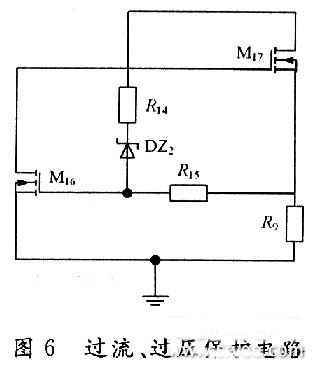
The overcurrent and overvoltage protection circuit of the power tube in the CMOS automotive electronic regulator is shown in Fig. 6. In Figure 6, the M17 tube is the excitation current adjustment tube (ie, the high power tube), the resistors R9 and M16 form the overcurrent protection circuit, and the resistor R14 regulator tube DZ2 and M16 tubes form the overvoltage protection circuit for the power tube, of which M16 and M14 The tube is also used as a switch tube.
3 overall circuit and simulation
3.1 circuit integration
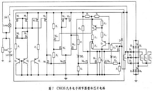
According to the above design of the various parts of the regulator chip, combining them together is the overall circuit of the regulator to be designed, as shown in FIG.
3.2 Functional verification
The simulation verification waveform is shown in Figure 8, where the abscissa is the generator output voltage and the ordinate is the change in the base voltage of the excitation regulator. Figure 8(a) shows the verification waveform at a fixed temperature, and Figure 8(b) shows the verification waveform at full temperature.
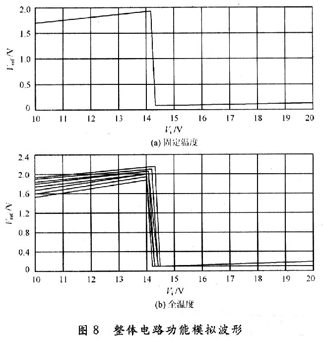
It can be seen from Fig. 8 that when the voltage at the output of the generator does not reach the regulation voltage, the base potential of the regulator approaches zero potential, and the adjustment tube is turned off. It can be seen from Fig. 8(b) that the regulator can still obtain good regulation performance at different operating temperatures.
4 Conclusion
A monolithic CMOS automotive electronic regulator is proposed. The chip mainly adjusts the current in the excitation coil of the generator by controlling the conduction and the cut-off of the adjustment tube, thereby stabilizing the output voltage. The automobile power generation system composed of the chip has the characteristics of high reliability, small number of peripheral components, low cost and convenient use, and is of great significance for breaking the monopoly of foreign automobile core technology.
Single-axis motion phase stabilizer is a pivoted support that allows the sport cam like Gopro staying stabilized. With a gyro-stabilized gimbal system, it keeps stabilized or steerable horizon with automatic calibration to give you an unprecedented smooth shooting experience.

Sport cam gimbal are designed as pocket size, portable and easy to take. You can carry it as easy as smartphone!

Wewow focusing on handheld stabilizer is a technology company which does R & D independently. With Wenpod series product released, the company achieved the industry's praise and quickly became the leader of the smart stabilizer industry.
Our service
1. Reply to you within 24 hours.
2. Already sample: within 1-2days.
3. Shipping date: within 24 hours once get the payment.
4. 12 months warranty.
5. After-sales service, solve within 3 working dates.
If you have any questions, please contact with us directly.
Wewow appreciates domestic and international business relationship!
Single-axis Motion Phase Stabilizer
Single-Axis Motion Phase Stabilizer,Professional Single-Axis Motion Phase Stabilizer,Motion Phase Stabilizer With Single Handheld,Handheld Single-Axis Motion Phase Stabilizer
GUANGZHOU WEWOW ELECTRONIC CO., LTD. , https://www.stabilizers.pl