A 200W solar photovoltaic grid-connected inverter design solution can directly convert the DC power generated by the solar panel into a 220V/50Hz power frequency sinusoidal AC output to the grid.
A control system for a low-power photovoltaic grid-connected inverter: The topology of the DC/DC controller adopts a push-pull circuit, which is controlled by a chip SG3525, which effectively prevents bias, DC/AC inverter The device is a full-bridge inverter circuit, which is controlled by DSP. Because the computing speed of the DSP is relatively high, the output current of the inverter can well track the grid voltage waveform. The effectiveness of this photovoltaic grid-connected inverter control scheme was verified in the laboratory. The control system ensures that the output power factor of the inverter is close to 1, and the output current is sinusoidal.

System working principle and its control scheme
1 Photovoltaic grid-connected inverter circuit principle
The main circuit schematic diagram of the solar photovoltaic grid-connected inverter is shown in Figure 1. In this system, the solar panel outputs a rated voltage of 62V DC, which is converted to 400V DC by a DC/DC converter, and then 220V/50Hz AC is obtained after DC/AC inverter. The system ensures that the 220V / 50Hz sinusoidal current output by the grid-connected inverter is synchronized with the phase voltage of the grid.
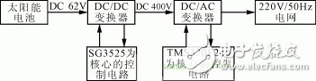
Figure 1 circuit block diagram
2 system control scheme
2 is a main circuit topology diagram of a photovoltaic grid-connected inverter, which is composed of a DC/DC converter of a front stage and a DC/AC inverter of a subsequent stage. The inverter circuit of the DC/DC converter can be selected from the group consisting of a half bridge type, a full bridge type, and a push pull type. Considering that the input voltage is low, if the half-bridge type is used, the switching tube current becomes larger, and the full-bridge type is complicated in control and the switching tube power consumption is increased. Therefore, a push-pull circuit is used here. The DC/DC converter is composed of a push-pull inverter circuit, a high-frequency transformer, a rectifier circuit and a filter inductor, and converts a 62V DC voltage output from the solar panel into a DC voltage of 400V.
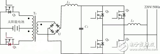
Figure 2 main circuit topology
The main circuit of the DC/AC inverter adopts a full-bridge structure, which consists of four MOS tubes (parallel antiparallel diodes inside the tube), which converts 400V DC into 220V/50Hz power frequency AC.
2.1 DC / DC converter control scheme
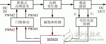
Figure 3 Control block diagram of the DC/DC converter
LED Street Light which semiconductor lighting, light emitting diode as light source, because it is a solid cold light source, green pollution-free, less consumption, high luminous efficiency, long service life etc, made of LED street light.
LED Street Light is applicable to road, highway, highways, urban streets, sidewalks and other road lighting and square, schools, industrial zone, parks and other outdoor lighting.
LED Street Light
LED Street Light,LED Solar Street Light,Adjustable LED Street Lighting,Solar Panel LED Street Light,Outdoor Light
Wenzhou Korlen Electric Appliances Co., Ltd. , https://www.korlenelectric.com