In 2014, the domestic production and sales of new energy vehicles exceeded 80,000, and the development trend was gratifying. In order to enable new energy enthusiasts and junior R&D personnel to better understand the core technologies of new energy vehicles, the author combined the experience in the R&D process and analyzed the new energy vehicle classification, module planning, electronic control technology and charging facilities.
1 new energy vehicle classification
In the classification of new energy vehicles, the different classification methods of “weak mixing, strong mixing†and “series, parallel†are confusing for non-industry people. In fact, these names are explanations from different angles and are not contradictory.
1.1 Consumer perspective
The consumer perspective is usually divided according to the degree of mixing, which can be divided into starting and stopping, weak mixing, medium mixing, strong mixing, plugging and pure electric, fuel saving effect and cost increase, as shown in Table 1. The "-" in the table indicates that there is no such function or is weak, and the more "+" the number indicates the better the effect. It can be seen from the table that as the fuel saving effect is improved and the cost is increased.

1.2 technical perspective

The technical perspective is from simple to complex, pure electric, series hybrid, parallel hybrid and hybrid hybrid, as shown in Figure 1. P0 represents the BSG (Belt starter generator) system, P1 represents the ISG (Integrated starter generator) system, the motor is between the engine and the clutch, and the motor in P2 is in the clutch and Between the transmission inputs, P3 indicates that the motor is at the transmission output or is disposed on the rear axle, and P03 indicates a combination of P0 and P3. It can be seen from the statistical table that various structures are widely used in passenger or commercial vehicles at home and abroad. Relatively speaking, P2 is popular in Europe, and the planetary row structure is dominant in Japanese and American vehicles, such as P03. The structure is widely used in four-wheel drive vehicles, and the Outlander and Peugeot 3008 have been mass-produced. The selection of new energy vehicles should take into account structural complexity, fuel economy and cost increases. For example, the three-planetary dual-mode system jointly developed by GM, Chrysler and BMW, despite the better fuel economy, is complicated and costly. The market performance in the past decade has not been satisfactory.
2 New energy vehicle module planning
Although the classification of new energy vehicles is complex, there are many modules shared among them. Modular methods can be used in the development process to share platforms and improve development speed. In general, the whole new energy vehicle can be divided into three-level module system, as shown in Figure 2. The first-level module mainly refers to the execution system, including charging equipment, electric accessories, energy storage system, engine, generator, clutch, and drive. Motor and gearbox. The secondary module is divided into two parts: the execution system and the control system. The execution part includes the ground charger, the current collector and the vehicle charger of the charging device, the unit of the energy storage system, the electric box and the PACK, the gas part of the engine part, the gasoline engine and Diesel engine, permanent magnet synchronous and AC asynchronous of the generator, dry and wet in the clutch, permanent magnet synchronous and AC asynchronous of the drive motor, stepped automatic transmission (including AMT, AT and DCT, etc.) in the gearbox section, planet Row and reduction gear; the control system of the secondary module includes BMS, ECU, GCU, CCU, MCU, TCU and VCU, respectively representing battery management system, engine electronic control unit, generator controller, clutch control unit, motor controller, Transmission control system and vehicle controller. The three-level module system includes the power type and energy type of the battery unit, the water-cooling and air-cooling forms of the permanent magnet and the asynchronous motor, and the three-level module of the control system mainly includes the hardware, the bottom layer and the application layer software.

According to the similarity of function and control, some modules of the three-level module system can form pure electric (including extended program), plug-in parallel hybrid and plug-in hybrid hybrid platform architecture, such as pure electric (including extended program) It consists of charging equipment, electric accessories, energy storage system, drive motor and gear box. The platform modules are highly versatile. Using platform and module development methods, they can share core component resources, improve the security and reliability of new energy systems, shorten cycle times, and reduce R&D and procurement costs.
3 new energy vehicles three core technologies
In the three-level module system and platform architecture, the vehicle controller (VCU), motor controller (MCU) and battery management system (BMS) are the most important core technologies for the power, economy and reliability of the vehicle. And security, etc. have a major impact.
3.1VCU
The VCU is the core electronic control unit for realizing vehicle control decisions. Generally, only new energy vehicles are equipped, and conventional fuel vehicles do not need this device. The VCU judges the driver's driving intention by collecting signals such as the accelerator pedal, gear, brake pedal, etc.; by monitoring the vehicle status (vehicle speed, temperature, etc.) information, after the VCU judges the process, the vehicle is sent to the power system and the power battery system. The state control command simultaneously controls the working mode of the vehicle accessory power system; the VCU has the vehicle system fault diagnosis protection and storage function.
Figure 3 shows the structure of the VCU, including the shell, hardware circuit, low-level software and application layer software. The hardware circuit, the underlying software and the application layer software are the key core technologies of the VCU.
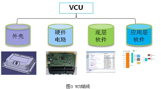
The VCU hardware is designed with standardized core module circuits (32-bit main processor, power supply, memory, CAN) and VCU dedicated circuits (sensor acquisition, etc.); the standardized core module circuits are portable for MCU and BMS, and the platform hardware will be very Good portability and scalability. With the development of automotive-grade processor technology, VCU has gradually transitioned from 16-bit to 32-bit processor chips, and 32-bit has become the mainstream product in the industry.
The underlying software adopts the AUTOSAR automotive software open system architecture as the standard, achieves the development goal of the electronic control unit (ECU) development common platform, supports different control systems of new energy vehicles; modular software components aim at software reuse to effectively improve Software quality and shorten software development cycle.
The application layer software is developed according to the V-type development process and based on the model, which is beneficial to teamwork and platform development. The rapid prototyping tool and the model-in-the-loop (MIL) tool are used to verify the software model, speeding up the development; the policy document and the software model are both Management with dedicated version tools for enhanced traceability; driver torque analysis, shifting rules, mode switching, torque distribution and fault diagnosis strategies are key technologies at the application level for vehicle dynamics, economy and reliability Has an important impact.
Table 2 shows the technical parameters of the world's mainstream VCU suppliers, representing the development of the VCU.

3.2 MCU
The MCU is a core power electronic unit unique to new energy vehicles. It controls the motor to output the specified torque and speed by receiving the vehicle's driving control command from the VCU to drive the vehicle. The utility model realizes converting the DC electric energy of the power battery into the required high-voltage alternating current, and driving the motor body to output mechanical energy. At the same time, the MCU has motor system fault diagnosis protection and storage functions.
The MCU consists of a housing and cooling system, a power electronics unit, a control circuit, an underlying software, and control algorithm software. The specific structure is shown in Figure 4.
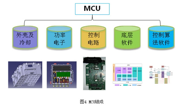
MCU hardware circuit adopts modular and platform design concept (core module and VCU same platform), power drive part adopts multiple diagnostic protection function circuit design, power circuit part adopts automotive grade IGBT module parallel technology, customized bus capacitor and integrated busbar design The structural part adopts high protection level and integrated integrated liquid cooling design.
Similar to VCU, the underlying software of MCU is based on AUTOSAR open system architecture, which achieves the development goal of ECU development common platform, and modular software components aim at software reuse.
The application layer software can be generally divided into four modules according to the function design: state control, vector algorithm, demand torque calculation and diagnosis module. Among them, the vector algorithm module is divided into MTPA control and field weakening control.
MCU key technical solutions include: based on 32-bit high-performance dual-core main processor; automotive-grade parallel IGBT technology, custom-made thin film bus capacitors and integrated power loop design, based on AutoSAR architecture platform software and advanced SVPWM PMSM control algorithm; high protection grade housing And integrated integrated water cooling design.
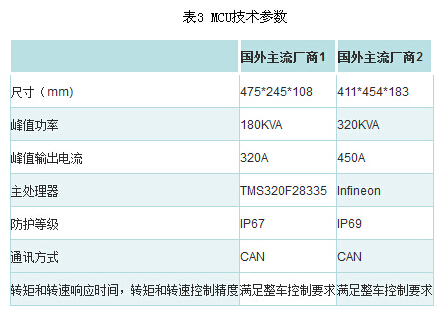
Table 3 shows the technical parameters of the world's mainstream MCU hardware suppliers, representing the development of the MCU.
3.3 battery pack and BMS
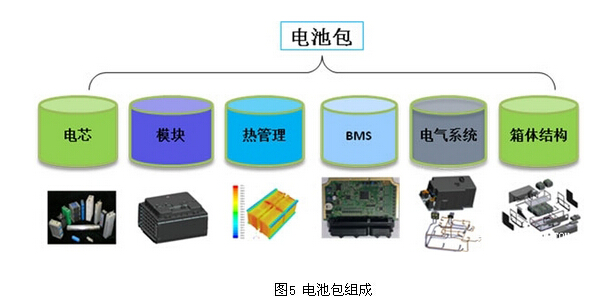
The battery pack is the core energy source of the new energy vehicle, which provides driving energy for the whole vehicle. It mainly forms the battery pack main body through the metal casing envelope. The modular structure design realizes the integration of the battery core, optimizes the thermal management performance of the battery pack through thermal management design and simulation, and the electrical components and wiring harness realize the safety protection and connection path of the control system to the battery; realize the management of the battery core through BMS And communication and information exchange with the whole vehicle.
The battery pack is composed as shown in Figure 5, including batteries, modules, electrical systems, thermal management systems, cabinets, and BMS. BMS can improve battery utilization, prevent overcharging and overdischarging of batteries, extend battery life, and monitor battery status.
BMS is the most critical component of the battery pack. Similar to the VCU, the core part consists of hardware circuits, low-level software and application layer software. But the BMS hardware consists of two parts: the main board (BCU) and the slave board (BMU). The slave board is installed inside the module to detect the voltage, current and equalization control of the unit. The motherboard is installed in a flexible position for relay control and charge. Electrical state value (SOC) estimates and electrical damage protection.
The BMU hardware part performs battery cell voltage and temperature measurement, and performs bidirectional transmission of instructions and data through the highly reliable data transmission channel and the BCU module. The BCU is available with a 32-bit microprocessor based on the automotive functional safety architecture for total voltage acquisition, insulation detection, relay drive and condition monitoring.
The underlying software architecture conforms to the AUTOSAR standard, and modular development facilitates expansion and portability to improve development efficiency.
Application layer software is the control core of BMS, including battery protection, electrical damage protection, fault diagnosis management, thermal management, relay control, slave board control, equalization control, SOC estimation and communication management. The application layer software architecture is shown in Figure 6. Show.
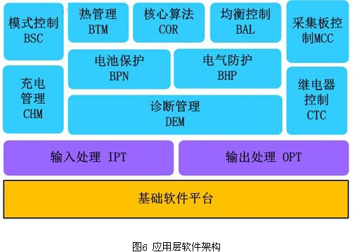
Table 4 shows the technical parameters of mainstream BMS suppliers at home and abroad, representing the development of BMS.

4 charging facilities
Inadequate charging facilities are an important factor hindering the promotion of new energy vehicles. They analyze the successful solutions of Tesla and propose charging solutions for new energy vehicles and analyzing the composition of charging systems.
4.1 Tesla charging scheme analysis
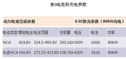
The Tesla Super Charger represents the most advanced charging technology in the world. It charges the MODEL ($6.3420) S much faster than most charging stations. Table 5 shows the Tesla battery and charging parameters.
Tesla has 5 charging modes, charging with ordinary 110/220V mains socket, 30 hours full; integrated 10kW charger, 10 hours full; integrated 20kW charger, 5 hours full; a fast charger can be loaded In the home wall or parking lot, the charging time can be shortened to 5 hours; 45 minutes can charge 80% of the electricity, and the electricity fee is free. This fast charging device is only common in the North American market.
Tesla uses a solar panel awning charging station that both offsets energy consumption and shades. Unlike the cost of refueling at a gas station, the properly configured MODEL ($6.3420) S can be recharged free of charge at any open charging station.
The characteristics of Tesla's charging technology can be summarized as follows: 1) The Tesla charging station incorporates solar charging technology, which enables the charging station to use clean energy as much as possible, reducing the dependence on the grid, and also reducing the grid. Interference, this technology in the country can also be achieved. 2) Tesla's charging time is not surprising. Tesla's charger capacity is 90~120kWh, and the charging rate is 0.8C. Like ordinary fast charging, it does not use a larger charging rate, so it will not affect the battery. Lifespan; 20% to 40%, can meet the endurance requirements, the main reason is the battery capacity.
4.2 charging solution
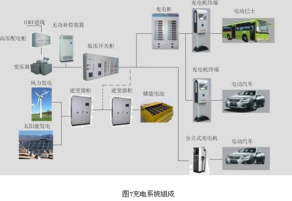
Figure 7 shows a new energy vehicle charging solution that can be referenced. The charging system consists of: distribution system (high-voltage power distribution cabinet, transformer, reactive power compensation device and low-voltage switchgear), charging system (charging cabinet and charger terminal). And energy storage system (energy storage battery and inverter cabinet). The reactive power compensation device solves the influence of the charging system on the power factor of the power grid. The charging machine in the charging cabinet generally has an active filtering function to solve the problem of harmonic current and power factor. The energy storage battery and the inverter cabinet solve the problem that the old power distribution system can not meet the capacity requirements of the charging station, and play the role of peaking and filling the valley. When the energy is not charged, the large capacity charging and the capacity of the power distribution system are insufficient. Store energy for charging. If the capacity of the new power distribution system is sufficient, the energy storage battery and the inverter cabinet may not be used. Wind power and photovoltaic power provide clean energy to the charging system, minimizing power take-off from the grid.
5 summary
From the perspective of consumers and technology, the new energy vehicle structure is classified and analyzed, and the advantages of various structures are analyzed, as well as the application status of various domestic and foreign OEMs. Analyze the module composition and platform architecture of the new energy vehicle, and introduce the relevant execution system and control system in the three-level module system in detail. Analyze the structural composition and key technologies of VCU, MCU and BMS, as well as the technical parameters and development trends of mainstream suppliers in the world. Analyze Tesla's successful solutions and propose charging solutions for new energy vehicles.
Doorbell speaker:
Doorbell speaker is a kind of micro speaker unit which uses a diaphragm made of Mylar material. Doorbell speakers are of ultrathin design and lightweight and clear voice. It is widely used in building security industry (e.g. intercom, video door phone, intelligent door control..)
There are two types of Mylar speakers from the shapes:
1) Round shapes, we have products from 10mm to 57mm in diameter.
2) Oblong shape, we have products in sizes of 1510/1712/1813-..


FAQ
Q1. What is the MOQ?
XDEC: 2000pcs for one model.
Q2. What is the delivery lead time?
XDEC: 15 days for normal orders, 10 days for urgent orders.
Q3. What are the payment methods?
XDEC: T/T, PayPal, Western Union, Money Gram.
Q4. Can you offer samples for testing?
XDEC: Yes, we offer free samples.
Q5. How soon can you send samples?
XDEC: We can send samples in 3-5 days.
Doorbell Speaker,Doorphone Speaker,Video Doorphone Speaker,Doorbell Wireless Speakers
Shenzhen Xuanda Electronics Co., Ltd. , https://www.xdecspeaker.com