The 5.1 version of COMSOL MulTIphysics introduces a new UHF RFID tag tutorial model. RFID tags allow you to identify and monitor abiotics and creatures by using electromagnetic fields. UHF RFID tags are used in a wider range of applications than other types of RFID tags and are commonly used for animal identification. We can evaluate the performance of the tag by analyzing the electric field and far field radiation patterns.
Use RFID tags for animals
Radio Frequency Identification (RFID) tags are used to identify objects under a wireless connection. They can be used in a variety of applications, from ID documents to animal care, and even more creative and sci-fi uses: as part of a machine butterfly. Scientists also use RFID tags to track the whale shark, the largest fish in the ocean. I hope to learn more about these gentle marine life. RFID tags are more commonly used on farm animals. Farmers tag animals such as cows to prove ownership of the animals, prevent theft, and identify the animals in the event of a sudden outbreak of disease.

Cows with RFID tags on their ears. (Image courtesy of Man vyi. Licensed by public domain and shared by Wikimedia Commons).
UHF RFID tag
There are currently three types of RFID tags:
Low frequency (LF) range
High frequency (HF) range
Ultra High Frequency (UHF) Range
Compared to other RFID, UHF RFID tags have many advantages, making them ideal for animal monitoring. Unlike HF tags, UHF RFID tags support reading at nearer and farther distances, so they have a wider range of applications. These tags typically transmit data faster than low- and high-frequency tags and are more competitively priced.
Modeling UHF RFID tag design (except animals)
The COMSOL MulTIphysics 5.1 release adds a tutorial model to help you start simulating passive UHF RFID tags. Let's see what is included in the tutorial.
When designing RFID tags, it is more common to bend the antennas in the model back and forth to make the overall label smaller. The antenna consists of copper lines patterned on the FR4 board. The lumped port represents the microchip that will be used to excite the tag and analyze the input impedance of the tag antenna. The lumped port has a reference impedance of 50 Ω. Near the bend line is another copper strip that is used to control the impedance.
All of these components are covered with a yellow, low-dielectric PTFE layer that looks similar to the one we see on the cow's ear.
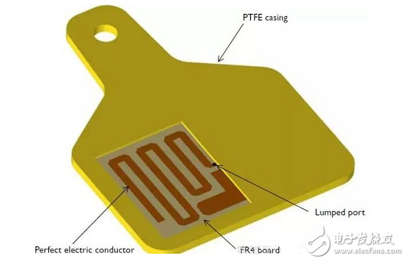
UHF RFID tag geometry, half of the board is exposed. The lumped port represents the chip.
Since we set the operating frequency of the RFID tag to 915 MHz and the copper line is thicker than the skin depth, the metal part of the design can be modeled as a perfect electrical conductor (PEC). Although not shown in the above figure, the entire model is surrounded by an air domain, which itself is wrapped by a perfectly matched layer (PML). The PML layer absorbs all outward radiation.
We deal with the complex impedance by selecting the power wave reflection coefficient term, using an unconventional simulation. It is therefore possible to calculate the matching properties in the RFID tag.
Note: We will jump directly to the results section in the next section. If you want to learn to build this tutorial model step by step, please visit the App library.
Evaluate label performance
Once the model is built and solved, we can analyze the results to evaluate the performance of the label design. To understand the distribution of the electric field throughout the antenna, an electric field mode plot can be studied. When the antenna resonates, a stronger field is observed outside each end and part of the bend line. The impedance matching between the antenna and the chip can determine the range of the tag.
First, we analyze the default electric field mode (E-field) of the xy plane to determine the limits of the electric field in the tag. As shown in the figure below, the electric field is symmetrical along the bend line and the space between the bend line and the impedance matching band. This is a very ideal situation because a symmetric field can produce a symmetric radiation pattern.
In symmetric radiation mode (in this model, an omnidirectional pattern on a plane), we can easily guess the optimal angular configuration of the label. In this use case, it is possible to determine from which location the tag is attached to the cow and determine the location of the RFID reader to ensure that all cows are monitored.
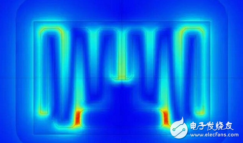
E-field mode drawing of a full-size board UHF RFID model.
Next, we can look at the far field radiation pattern. Simulation engineers who are working on other antenna designs will also be familiar with this mode; this radiation pattern looks a lot like a half-wave dipole antenna.
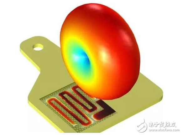
The far-field radiation pattern of the UHF RFID tag model.
Through simulation, we found that the power-wave reflection coefficient of the tag is less than –15 dB compared to the impedance of the chip 18+j124 Ω. This means that when the power delivered to the RFID chip is again radiated by the tag, the power reflected back to the chip will be less than -15 dB. Comparing this design with a common performance commercial antenna that provides -10 dB of power, our design is not the best, but it is perfectly acceptable. Since the radiation pattern is an omnidirectional mode around the bend line, its response in any direction on the same plane is substantially the same. This shows that our label is very stable and reliable.
If you are a design engineer at an RFID tag company, you can use the COMSOL MulTIphysics simulation software to evaluate the performance of UHF RFID tags. You can start by downloading the following tutorial model.
3Pans Buffet Server,Electric Warming Tray Buffet Server,Buffet Server Warming Tray,3Pans Buffet Server Warmer
Shaoxing Haoda Electrical Appliance Co.,Ltd , https://www.hotplates.nl