Button anti-shake circuit control circuit
The circuit using the RC integration circuit to achieve clutter filtering and waveform trimming is shown (Figure 1).
At the moment of S1 ON, due to the contact bounce, the voltage at point A will exhibit a high-speed intermittent phenomenon, and then S1 OFF
The time is also the same (as shown in Figure 2). However, since the voltage across the capacitor needs to be slowly charged by the voltage through the resistor, it will rise, so that the potential of the B point rises slowly: S1 OFF, the capacitor voltage passes through R. Discharge
The voltage at point B drops slowly. This change, after trimming in reverse with Schmitt, yields a standard negative pulse output, as shown by the waveform point C.
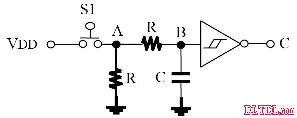
figure 1
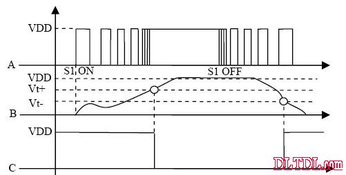
figure 2
Indoor Fine Pitch LED Panel,Fine Pitch LED Display,Full Color LED Display,Fine Pixel Pitch LED Display
ShenZhen UHLED Technology Co., LTD. , https://www.uhled.com