Abstract: Design an intelligent vehicle instrument based on WinCE operating system, receive the information of the ECU of each part of the car through the CAN bus, and display it in the liquid crystal display. Based on the S3C2440 microprocessor of ARM9 core, the peripheral hardware and the underlying driver and upper application of CAN bus in WinCE are designed.
Keywords: embedded application; intelligent vehicle instrument; WinCE; CAN bus
Introduction With the development of high-performance electronic display technology, the degree of electronic instrumentation is becoming more and more high. High-tech products such as multi-function electronic display instruments, head-up display instruments, car navigation systems, and driving recorders have been developed at home and abroad. In the future, automotive electronic embedded instruments have the following advantages: providing a large amount of complex information, making the electronic control of automobiles more and more high; meeting the requirements of small size and light weight, making the limited driving space more humanized; The high reliability realizes the electronicization of the automobile instrument and reduces the incidence of the fault; the online fault diagnosis system is provided, and once the vehicle is faulty, the source of the fault can be found and the maintenance is convenient; the shape design freedom is high, and the automobile instrument panel is beautiful in appearance. Based on the above advantages, automobiles will increasingly adopt electronic instruments for various purposes. The embedded electronic instrument with novel shape and powerful function will be the development trend and trend of vehicle instrument in the future.
1 Intelligent vehicle instrument system structure The intelligent vehicle instrument has the functions possessed by most traditional vehicle instruments. The driver can obtain the current car status information through the display interface of the vehicle instrument, such as vehicle speed, oil pressure, oil temperature, water temperature and oil pressure. Or battery power.
The traditional vehicle instrument is directly connected to the sensor of the vehicle, and the instrument system obtains the current state of the car through the analog quantity of the sensor, and the accuracy is not high. The intelligent vehicle instrument designed in this paper is not simply connected to the sensor, but the whole vehicle is connected into a network structure through the CAN controller. The vehicle components are equipped with a CAN controller, and the vehicle components are connected by twisted pairs to form a network system to realize the electronic components. At the same time, the electronicization of on-board instruments and automotive components also improves the accuracy and reliability of the car and reduces the incidence of failures.
The vehicle intelligent instrument is mainly divided into two parts: the hardware system based on S3C2440 processor and the software system based on WinCE environment. The hardware system provides the basis for the entire control system and is responsible for CAN bus communication. The software system provides hardware drivers for the CAN bus and instrumentation applications under WinCE.
2 hardware design hardware system with S3C2440 as the core, RAM memory, NOR Flash and NAND Flash as storage medium, expand part of peripheral equipment to be responsible for system information input and output, such as CAN bus communication unit, LCD display, touch screen, universal serial port , USB devices, Ethernet interfaces, etc. The system hardware structure is shown in Figure 1.
This article refers to the address: http://
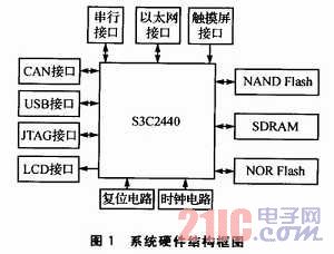
Among the many interfaces, the CAN bus communication unit is a key part in the vehicle communication process. In each important part of the car, the corresponding CAN control unit is configured, and the CAN bus control units are connected by twisted pairs. Each component of the vehicle is sent by the CAN control unit to the current state information of the component, and is sent to the CAN unit of the intelligent vehicle instrument via the twisted pair cable, and the data is sent to the system through the CAN interface of the system. After the vehicle instrument system obtains the data, the current state information of the automobile component is obtained through data processing.
The CAN bus interface circuit is shown in Figure 2. The chipbus controller MCP2515 from Microchip is used. The MCP2515 fully supports the CAN 2.OA/B specification and speeds up to 1 Mbps; the SPI interface standard makes it simpler to connect to the S3C2440; it can send and receive standard and extended data frames as well as remote frames; comes with 2 acceptance mask registers and Six acceptance filter registers can filter out unwanted messages, reducing microprocessor overhead. The CAN bus transceiver uses the TJA1050, which provides an interface between the CAN controller and the physical bus and differential transmit and receive functions for the CAN bus.
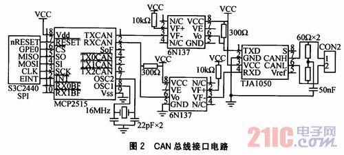
In order to enhance the anti-interference ability of the CAN bus node and improve the stability of the system, an optocoupler isolator 6N137 is added between the CAN controller and the CAN transceiver instead of directly connecting the TXCAN and RX-CAN terminals to the transceiver. Electrical isolation between the CAN nodes on the bus is achieved. At the same time, this also solves the problem of level compatibility between the MCP2515 and the TJA1050, and also suppresses spikes and noise interference in the CAN network. The two power supplies used in the optocoupler part of the circuit must be completely isolated, otherwise it loses its meaning. The isolation of the power supply can be achieved by using a low-power power isolation module or a switching power supply module with a 5 V isolated output. Although these parts increase the complexity of the interface circuit, they improve the stability and security of the node.
At the CAN interface, two 60Ω resistors (120 Ω total) on the CAN communication line are used to increase the load and reduce echo reflection. This is a remedy for impedance matching. A capacitor is connected between the two 60 Ω middle sections and the ground to prevent interference.
3 Software Design The overall environment of the software is the winCE programming environment. The corresponding WinCE operating system is customized for the in-vehicle smart meter hardware system to realize the hardware driving. Then write the application, realize the operation of the system hardware by the specific operation of the application, that is, realize the function of the system. The key to this is the driver for the CAN controller. The CAN driver implements the operation of the application software to the CAN control unit and reads the data code in the CAN control unit.
3.1 System Development and Porting Embedded system development is the design of the system driver layer, the most important of which is the development and debugging of BSP. Therefore, the development of the underlying driver of intelligent vehicle instrumentation is particularly important.
Since the WinCE operating system is used, the Platform Builder is used to customize the WinCE operating system image. In Platform Builder, you can add drivers for some of the system's hardware (such as LCD screens, RAM), which have been written by Microsoft. Then start the bootloader, download the image file to the flash memory, and configure the operating system boot file boot. Ini.
3.2 CAN bus driver development Since CAN is an external device, it is necessary to write the CAN driver in a stream interface mode. The stream interface driver function is designed to closely match the usual file system APIs (such as Activate Dev-iee, ReadFile, WriteFile, and IOControl, etc.), that is, the stream interface driver behaves as a system file in the application, and the application passes the system file. The special file is operated to complete the operation of the device. Writing stream interface files mainly uses stream interface functions, that is, entry points for stream interface drivers, such as XXX_Init, XXX_Read, and XXX_Open. These stream interface files correspond to the corresponding API functions, allowing the application to be accessed to external devices by the corresponding functions.
As a stream interface driver, the CAN bus driver also has a set of standard functions for I/O operations. These functions are provided to the WinCE operating system kernel, they are the DLL files of the stream interface driver. When the CAN bus driver is dynamically loaded, the system is registered. CAN driver registry information: 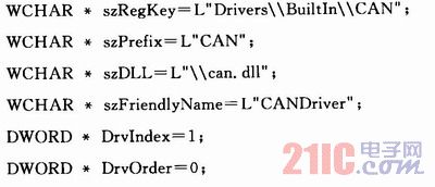
After completing the registration through the above code, call the ActivateDeviceEx() function to load the driver.
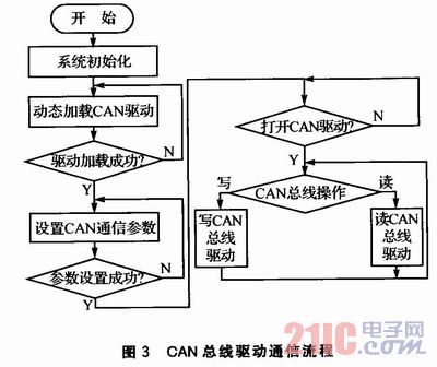
3.3 CAN bus driver communication flow CAN bus controller driver is mainly used to set the baud rate of MCP2515, MCP2515 acceptance filter, CAN message transmission mode and CAN transceiver data mode. The driver is an intermediate link between the host application and the hardware. The intelligent vehicle instrument system develops the CAN bus in the EVC++ environment.
The streaming driver opens the function CreateFile() as a file: After the driver is successfully opened, the CreateFile() function returns a handle that is not INVALID-HAN-DLE-VALUE. This handle also closes the parameter of the drive function Close-Handle(). The CAN setting function DeviceIoControl() receives the handle and control command code obtained by the CreateFile() function, and sets the input/output buffer and the size of the buffer. The size of the buffer that returns to the actual output after the function is completed. CAN bus send and receive functions WriteFile () and ReadFile (), using the driver file handle, send and receive buffer and other parameters to complete the data transmission and reception, after the operation is successful, return the actual number of bytes sent and received.
In order to prevent the main thread from waiting for the data to arrive, let the main thread have a time token to operate other things, the program uses a multi-threaded design to create a receiving data thread. The receiving data thread is an infinite loop that continuously queries the CAN bus data exit flag. If the exit flag is valid, the loop ends. The driver flow is shown in Figure 3.
Conclusion At present, on-board instruments based on embedded technology are gradually becoming popular. This paper uses WinCE-based ARM9 microprocessor as the development platform, which has fast processing speed and powerful functions. The CAN bus technology is used to transmit signals to each other. The CAN bus receives information sent by auto parts in real time, and processes and analyzes them. System, friendly interface. The intelligent on-board instrumentation system can save cost, reduce power consumption, and is highly maintainable, easy to expand and upgrade.
The Waterproof Bluetooth Earphone is wear comfortable, water-proof headphones. True wireless design is more convenient in running, gym, walking.... Also long work time, even with portable charging case, give you longer music experience.
Waterproof Bluetooth Earphone,Waterproof Bluetooth Earphones,Mini Bluetooth Earphone,Waterproof Sport Bluetooth Earphone
ShenDaDian(China) Digital Electronics Co.,Ltd , http://www.btearbuds.com